ENGLISH
21
3.3.3 Welding
preparations
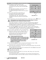
Open the chuck by pressing the ”Chuck left“ or
”Chuck right“ buttons and the upwards-arrow or pull
the control lever (
Item 4
).
Pipes smaller than 630 mm; fit the clamping insert for
the pipe diameter that has to be processed in the chuck
and then use the cotters to lock it in place.
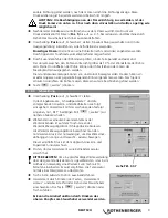
Fit the plastic pipe or the shaped piece that has to be
welded in the chuck and then close the chuck by
touching the ”Chuck left“ or ”Chuck right“ buttons
and the upwards-arrow or by pulling the control lever.
Tighten the brass nut of the chuck, and press the
button (“Continue“).
Danger of being crushed! Always keep a safe distance between you and the
machine when moving the clamp and the pipe towards one another!
In this case the pipe should be clamped in place so that the milling unit can be moved into
position easily and the pipe should protrude by about the same amount above the chuck.
The basic chuck can be exchanged for a special fittings chuck (accessory) that is used to
clamp shaped pieces in place.
Switch (
Item 6
) over to the “Welding“ icon and pull the control lever (
Item 4
) to the right,
moving the workpieces together with the relevant pressure (joining pressure) and verify
secure fit.
Traverse the table outwards until it is in the outer position.
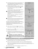
Traverse the milling unit inwards by touching the ”Milling
unit in / out“ button and the downwards-arrow or by
pulling the control lever.
You can lock the inwards or outwards traversing process
in place if you press the top button on the control lever
whilst the traversing process is running.
Danger of being injured! Never reach into the
moving blades during the commissioning of the
milling unit! The safety switch fitted to the milling
unit must be guaranteed to work at all times, in
order to prevent unauthorised switching on of the
machine from an external source!
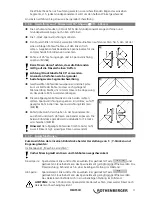
Switch (
Item 6
) the pressure setting over to the “Milling“ icon and then switch the milling
motor on by pressing the “Motor on“ button.
Pull the control lever over to the right to carefully traverse the end of the pipe so that it is up
against the milling unit’s rotating blade.
The milling contact pressure can be adjusted linearly using the pressure adjustment valve
(
Item 5
).
It must never exceed 15 – 20-bar
.
Note: Lock the pressure!
You can lock the milling pressure it in place after you have set it up by pressing the button
on the top of the control lever.
The direction indicator will flash after the locking process has been activated. The locking
process can be unlocked by pressing the button on the top of the control lever or by pulling
the control lever in another direction; the direction indicator will be extinguished after it has
been unlocked. The pressure locking process can be implemented at any time when running
other working processes.
see pt. 3.3.7
see pt. 3.3.7


