4
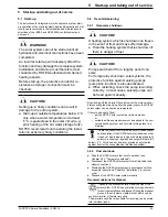
x
Installation
FA ROTEX Solaris DrainBack - 09/2016
17
4.2
System layouts
ROTEX solar systems are usually built according to one of the
following system concepts.
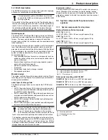
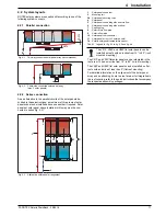
4.2.1 Parallel connection
4.2.2 Series connection
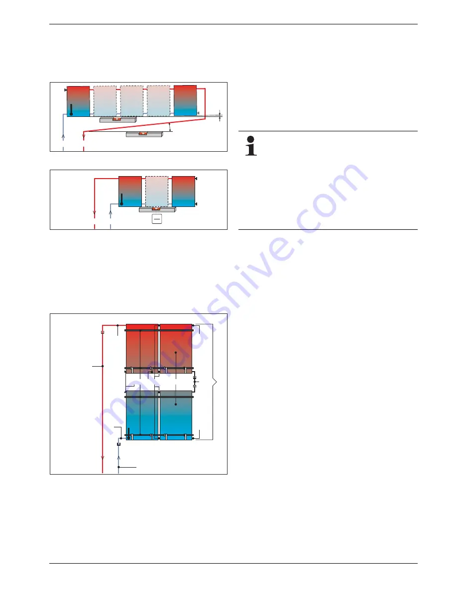
As an alternative to the parallel circuits of the solar panels de-
scribed in these instructions, a maximum of three rows of solar
panels can also be installed above one another if required. Solar
panels or solar panel arrays installed in this way must be con-
nected in series (fig. 4-3).
Fig. 4-1
Two-way connected solar panel array (recommended)
Fig. 4-2
Same-side connected solar panel array
(max. 3 solar panels)
Fig. 4-3
Alternative solar panel arrangement
≥0,5%
≥2%
T
K
9
8
T
K
9
8
1
2
10
11
5
6
9
8
7
7
7
2b
4
T
K
1
Solar panel connector
2
Mounting rail
2b
Solar panel securing clips
4
Solar panel
5
Solar panel connecting elbow return flow
6
Solar panel connecting elbow inflow
7
Sealing plug
8
Solar return flow pipe
9
Solar inflow pipe
10
Solar panel row connector
11
Solar panel array (2x 2 solar panels)
T
K
Solaris solar panel temperature sensor
Tab. 4-1 Legend for fig. 4-1 to fig. 4-3 and fig. 4-8
The V21P, V26P and H26P flat solar panels can be
installed on roofs with an incline from 15° to 80° (roof-
mounted mounting).
The V21P and V26P flat solar panels can be integrated in the
roof area if it has an incline from 15° to 80° (in-roof mounting).
The V26P and H26P flat solar panels can be installed on flat
roofs with an incline of less than 5° (flat roof mounting).
For detailed information on the alignment of the solar panel
array and on attaching it onto the roof area or for integration in
the roof covering, refer to the quick instructions that accompany
the respective assembly packages.

