background image

41

English

DISPLAY

D I S P L A Y

O P T I O N S

D I S P L A Y

S O U R C E : O f f

C O N T R A S T : -

3

B R I G H T N E S S : +

2

T F T

S C R E E N : O N

A L W A Y S

O S D

O U T P U T : S C R E E N + M o n .

M A I N

M E N U


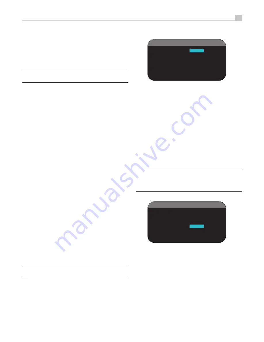
The DISPLAY menu controls the front panel LCD display

DISPLAY SOURCE:

 Specifies the video displayed on the front panel, 

choices are SOURCE, Composite 1 - 3, S-Video 1- 3, Component 1- 3, 
HDMI 1 - 4 and OFF.

CONTRAST:

 Adjust the contrast of the front panel display by highlighting 

and press SELECT.  Adjust between -63 to +63.

BRIGHTNESS:

 Adjust the brightness of the front panel display by highlighting 

and press SELECT.  Adjust between -63 to +63.

TFT SCREEN:

 Adjust the Front panel display to ON ALWAYS, OFF 

ALWAYS, SLEEP MODE.

OSD OUTPUT:

 Sets whether the OSD Menu is displayed on TV, Front 

panel display or Both.

Note:

 If the OSD Menu is turned off on the front panel display and no  

OSD is available on the TV.  A long press (5 seconds) of the DISPLAY 
key on the front panel and remote control will re-activate the front panel 
display.

EQ

E Q

O P T I O N S

E Q

E N A B L E : O f f

S P E A K E R : A L L

E Q

V A L U E : E n t e r

M A I N

M E N U

EQ ENABLE:


Select either ON or OFF to turn on/off the EQ feature.

SPEAKER: 

Select either ALL or Individual speakers using LEFT/RIGHT 

keys.

Press the ENTER button to go to confirmation screen where a 

2. 

password must be entered. The default password is 0000. If the 
entered password is correct, the current settings will be saved as 
the new USER DEFAULT settings.

To return to the MAIN menu without saving changes, change all 

3. 

entries on the screen to NO and press ENTER.

Note:

  If  there  is  insufficient  memory  to  store  a  USER  DEFAULT 

configuration file, the SET USER DEFAULT option will not be available.

To activate memorized USER DEFAULT settings:

 After you have stored a 

USER DEFAULT configuration file, you can activate those settings at any 
time by placing the highlight on the USER DEFAULT line using the Up/
Down buttons. Use the Left/Right buttons to change the setting to YES. 
Press the ENTER button to proceed with activating the USER DEFAULT 
settings. To return to the MAIN menu without activating the USER DEFAULT 
settings, change the entry to NO and press the ENTER button

To return to the MAIN menu without activating the USER DEFAULT settings, 
change the entry to NO and press the ENTER button.

To change the password:

 The password programmed at the factory is 

0000. If you wish to change the password:

Place the highlight on the SET NEW PASSWORD line using the Up/

1. 

Down buttons. Use the Left/Right buttons to change the setting to YES. 
Press the ENTER button to proceed to the PASSWORD screen.

Enter the four digits of the old password by pressing the Left/Right 

2. 

buttons to select the first letter of the new password, then pressing 
ENTER to move to the second character. Repeat until the old password 
is entered. Successful entry of the old password will jump to the 
ENTER NEW PASSWORD line.

Enter the four digits of the new password by pressing the Left/Right 

3. 

buttons to select the first letter of the new password, then pressing 
ENTER to move to the second character. Repeat until the new 
password is entered. 

You will be asked to re-enter the password again on the CONFIRM 

4. 

PASSWORD line, following the same procedure. Once the password 
is successfully confirmed, it will be saved and you will return to the 
DEFAULT SETUP MENU automatically.

To exit the PASSWORD screen without changing the password, 

5. 

highlight the DEFAULT SETUP MENU line and press ENTER to return 
to the previous screen.

Note:

 The factory password is 0000. A default password that will always 

be recognized is 8888.

Summary of Contents for RSP-1580

Page 1: ...Owner s Manual RSP 1580 Surround Sound Processor Register your product at www rotel com register RSP 1580 MENU MUTE DISPLAY INPUT MODE M O N STANDBY HDMI M O N FUNCTION ENT...

Page 2: ...4 Connection Figures Figure 1 Control and Connections 5 Figure 2 Remote Controller 6 Figure 3 Amplifiler and Subwoofer 7 Figure 4 Monitor Connections 8 Figure 5 DVD Blu ray Player and Cable Satellite...

Page 3: ...posal of Waste Electrical and Electronic Equipment WEEE The crossed wheelie bin symbol indicates compliance and that the products must be appropriately recycled or processed in accordance with these d...

Page 4: ...aution when moving the unit in a stand or rack to avoid injury from a tip over Immediately stop using the component and have it inspected and or serviced by a qualified service agency if The power sup...

Page 5: ...AL INPUT OPTICAL OPTICAL COAXIAL COAXIAL DIGITAL OUTPUT IN OUT L L R R COMPUTER I O IR OUT REM IN 12V TRIG OUT S VIDEO IN S VIDEO OUT COMPONENT VIDEO MON OUT Y Pb Pr Y Pb Pr HDMI IN HDMI OUT MONITOR M...

Page 6: ...6 RSP 1580 SURROUND SOUND PROCESSOR P EQ A B C D E G I K J H F Figure 2 Remote Control...

Page 7: ...T DIGITAL INPUT OPTICAL OPTICAL COAXIAL COAXIAL DIGITAL OUTPUT IN OUT L L R R COMPUTER I O IR OUT 12V TRIG OUT S VIDEO IN S VIDEO OUT COMPONENT VIDEO MON OUT Y Pb Pr Y Pb Pr HDMI IN HDMI OUT MONITOR M...

Page 8: ...O IR OUT 12V TRIG OUT S VIDEO IN S VIDEO OUT COMPONENT VIDEO MON OUT Y Pb Pr Y Pb Pr HDMI IN HDMI OUT MONITOR MON 2 MON 3 MON 4 RP 499C SERIAL NO POWER 480p 576p 720p 1080i 1080p HDTV S VIDEO COMPONE...

Page 9: ...35 other U S and worldwide patents issued pending DTS is a registered trademark the DTS logos and Symbol are trademarks of DTS Inc Copyright 1996 2007 DTS Inc All Right Reserved VIDEO OUT TAPE CD VIDE...

Page 10: ...R MON 2 MON 3 MON 4 RP 499C SERIAL NO POWER S VIDEO VIDEO COMPOSITE LINE OUT REC IN S VIDEO COMPOSITE AUDIO RIGHT LEFT LINE OUT RIGHT LEFT REC IN REM IN Figure 8 CD Player connections VIDEO OUT TAPE C...

Page 11: ...d trademark the DTS logos and Symbol are trademarks of DTS Inc Copyright 1996 2007 DTS Inc All Right Reserved Figure 10 AM FM Internet Radio Tunner Connections VIDEO OUT TAPE CD VIDEO IN TUNER MULTI I...

Page 12: ...INPUT OPTICAL OPTICAL COAXIAL COAXIAL DIGITAL OUTPUT IN OUT L L R R COMPUTER I O IR OUT 12V TRIG OUT S VIDEO IN S VIDEO OUT COMPONENT VIDEO MON OUT Y Pb Pr Y Pb Pr HDMI IN HDMI OUT MONITOR MON 2 MON...

Page 13: ...P E A K E R S E T U P M E N U T E S T T O N E F L 1 d B F R 2 d B C N T 1 d B S W 9 d B S L 4 d B S R 5 d B C B L C B R L V H 3 d B R V H 3 d B M A I N M E N U I N P U T S E T U P L I S T E N V i d e...

Page 14: ...issued pending DTS DTS HD and the Symbol are registered trademarks DTS HD Master Audio and the DTS logos are trademarks of DTS Inc Product includes software DTS Inc All Rights Reserved This item incor...

Page 15: ...nts in the system are connected to the unit s inputs with a pair of standard RCA cables for analog audio a video connection Composite S Video Component Video and or HDMI and an optional digital audio...

Page 16: ...o the same VCR Note The unit cannot convert S Video Component Video or HDMI signals to composite video signals at the record outputs Therefore only signals received at the composite video inputs are a...

Page 17: ...0p 24 1080p Composite 480i 576i S video 480i 576i 480i 576i 480p 576p 720p 60 50 1080i 60 50 480i 576i 480p 576p 720p 60 50 1080i 60 50 1080p 60 50 input video support 480i 576i 480p 576p 720p60 720p5...

Page 18: ...are consistent If you hook up a particular VCR to the VIDEO 1 inputs hook up the VIDEO 1 outputs to the same VCR Note There are no analog audio outputs for VIDEO 3 4 5 Therefore in an elaborate syste...

Page 19: ...ollowing section for additional information Note With a digital input connection the processor will be used to decode the signal rather than the source component s internal decoders You must use digit...

Page 20: ...te the relative volume levels of the speakers using the built in test tones See the Setup section of this manual Connecting a Subwoofer See Figure 3 To hook up a powered subwoofer connect a standard R...

Page 21: ...to your monitor S Video Analog connection Connect an S Video cable to the S VIDEO OUT output on the back of the processor Connect the other end of the cable to the S Video input on the TV Composite Vi...

Page 22: ...ce VIDEO 1 2 or 3 used for the previous connections If the recording device accepts a digital recording input connect one of the OPTICAL OUT or COAXIAL OUT connections to the digital input of the reco...

Page 23: ...er Rotel remote codes Push IR AUD key and 1 2 at the same time sets the remote control into IR code 1 2 Point the remote to the RSP 1580 and press 1 2 for 5 seconds sets the RSP 1580 in IR code 1 2 Th...

Page 24: ...cording During playback a Dolby Pro Logic or Pro Logic II decoder extracts each channel and distributes it to the appropriate speakers The original Dolby Pro Logic decoder delivered a mono signal with...

Page 25: ...Surround In 1999 the rst Dolby Digital soundtrack was released to theaters with an additional center back surround channel intended to increase the directional effects from behind the audience This ad...

Page 26: ...able all surround processing and deliver stereo signals to ampli ers and speakers The four options are 2CH Stereo Turns off the center channel and all surround channels in the system and delivers a co...

Page 27: ...or will be recognized and properly decoded However on a DVD with multiple soundtracks you must tell the DVD player which one to send to the processor For example you may need to use the DVD s menu sys...

Page 28: ...rueHD source there is an AUTO mode Dolby Digital 2 0 discs Dolby Digital decoding is auto detected and cannot be overridden You may however select 2 channel playback 5 1 channel playback with Pro Logi...

Page 29: ...also step through the DSP options MUSIC 1 4 5CH 7CH by repeatedly pressing the MODE button on the front panel Analog Stereo This type of recording includes any conventional stereo signal from the proc...

Page 30: ...ng you to enjoy movies and music and operate the system from a second third and fourth room From the remote location you can select a source component independent from the source playing in the main r...

Page 31: ...ngle supplied by Rotel SETUP The Rotel RSP 1580 features two types of information displays to help operate the system The rst consists of simple status displays that appear on the TV screen and or fro...

Page 32: ...Up Down and LEFT RIGHT buttons on the remote and press the SELECT button Press the MENU OSD button again to cancel the display and return to normal operation Con guring Inputs A key step in setting up...

Page 33: ...orarily overridden by the front panel or remote surround mode buttons Note Default surround modes are stored independently for the analog and digital inputs for each source Options for the default sur...

Page 34: ...odes for matrix decoding Use the LEFT RIGHT buttons on the remote to select a mode Select CINEMA to optimize for Dolby Surround encoded movie soundtracks including increased surround separation and fu...

Page 35: ...annels The subwoofer plays only the LFE channel bass Depending on the soundtrack there may be minimal use of the LFE channel so the subwoofer would be under utilized Meanwhile the normal bass places h...

Page 36: ...ng for maximum bass output with normal bass being duplicated by both the subwoofer and any LARGE speakers in the system C BACK F HEIGHT Select CENTER BACK if you have center back speakers installed or...

Page 37: ...you can use its built in low pass lter With the OFF setting a 100Hz high pass lter is activated for all SMALL speakers in the system Note The master crossover point can be overridden with a custom cro...

Page 38: ...dB dial setting with SLOW response and C weighting held away from your body at your listening position mounting the SPL meter on a camera tripod makes this easier You can point the SPL meter at each s...

Page 39: ...utton and the remote ON OFF buttons are disabled and the unit cannot be put in standby mode In RESUME mode the unit will return to the last power condition setting when switched on For example when th...

Page 40: ...s the selection A V SELECT VIDEO INPUT If the SOURCE selected above is A V SEL then you can specify the particular analog Video source Available sources are Composite 1 3 S Video 1 3 Component 1 3 and...

Page 41: ...be available To activate memorized USER DEFAULT settings After you have stored a USER DEFAULT con guration le you can activate those settings at any time by placing the highlight on the USER DEFAULT...

Page 42: ...turned up Make sure that preamp outputs are connected to a power ampli er and that the ampli er is turned on Make sure source inputs are connected and con gured correctly Check that the setting for H...

Page 43: ...y video enhancements such as Deep Color or XY video also called Broad Color Space Using the HDMI 1 4 connection the RSP 1580 can pass these signals through from the Blu ray player to a compatible moni...

Page 44: ...Version 1 4 supporting 3D passthrough General Power Consumption 100 watts 0 5 watt standby Power Requirements AC 120 volts 60Hz USA version 230 volts 50Hz EC version Weight 14kgs 31lbs Dimension W x H...

Page 45: ...th Reading MA 01864 2699 USA Phone 1 978 664 3820 Fax 1 978 664 4109 Rotel Europe Dale Road Worthing West Sussex BN11 2BH England Phone 44 0 1903 221 761 Fax 44 0 1903 221 525 Rotel Deutschland Vertri...

Reviews: