background image


LMA8 Mic/Line Preamplifier


17 


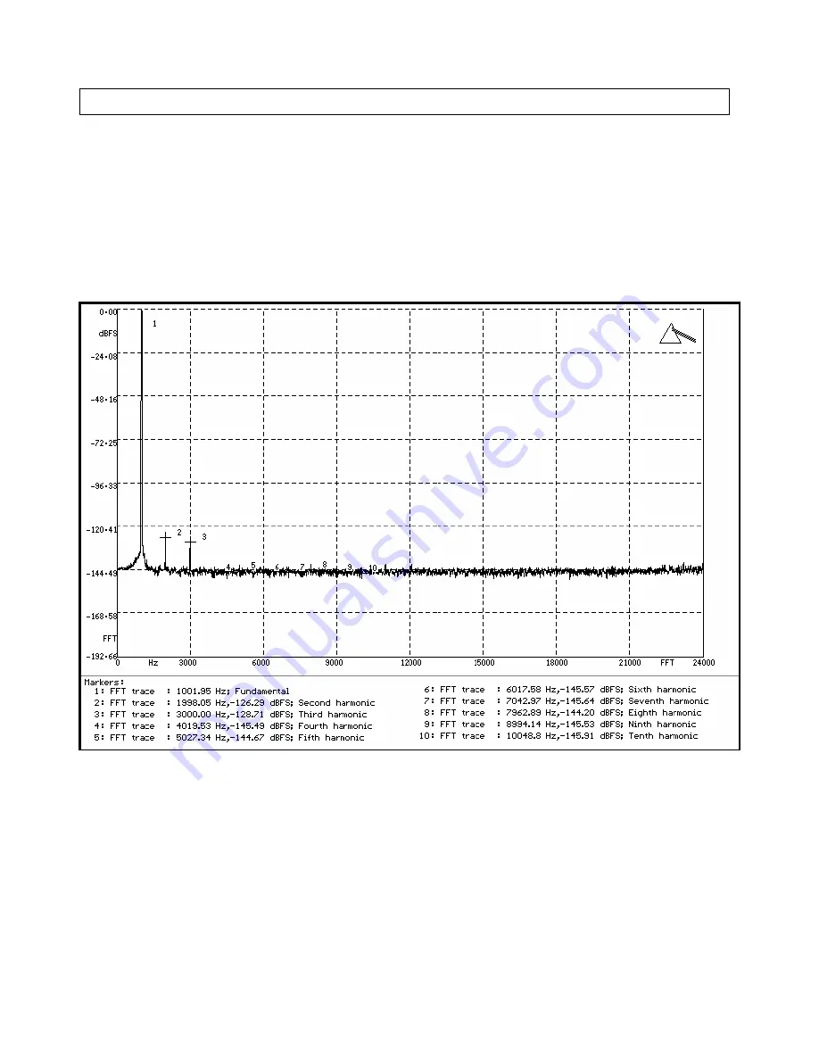
FFT distortion analysis 
 
FFT analysis has the ability to detect distortion that is buried in the noise. Noise is a statistical phenomenon, and by 
reading several samples and adding them together, the FFT analysis is able reduce the noise to its average value, thus 
revealing the distortion components otherwise buried in the noise. 
 
Below are plots of the distortion characteristics at various gain settings. Distortion levels are listed for 2nd to 10th 
harmonic and are quantified in dBFs. As a guideline, 120 dBFs equals 0.0001 %, 140 dBFs equals 0.00001 % 


             Gain +10 dB, frequency 1 kHz. The rms sum of all distortion components (THD) is 0.00013 % 


Summary of Contents for LMA8

Page 1: ...Phone 45 3967 6438 Fax 45 3966 6438 Website www rostec dk E mail rostec rostec dk LMA8 Mic Line Preamplifier 0 ROSTEC LMA8 8 channel Professional Mic Line Preamplifier Revision 5 March 23 2016 ...

Page 2: ...48 V Phantom Voltage 4 Input gain adjust 5 Status indicators 5 Mic inputs 6 Line outputs 6 Direct inputs 7 Digital interface slot 7 Remote ground connection 8 Front and back panel quick guide 9 Mechanical and electrical specifications 10 Technical section Clipping characteristics 11 Impulse response 11 Unwanted HF feedback 12 Noise performance and crosstalk 13 Classical distortion analysis 15 FFT ...

Page 3: ...ns an extremely fast and totally precise response The architecture is fully balanced throughout the unit which means that the signals between the various circuits are routed as a positive and a negative signal not the standard way of using signal and ground Ground is not used to transfer audio signals at all This architecture keeps the audio path free from non linear distortion from currents runni...

Page 4: ...LMA8 Mic Line Preamplifier 3 ...

Page 5: ...e toggle switch controls the bypass function of the insert point The insert point exists electrically between the output of the preamp and the input of the digital module When the LED is ON the signal chain between the preamp and the digital module is open which means that external equipment can then be inserted between line output insert send and the insert return direct input When the LED is OFF...

Page 6: ... dB from input to the line output on the D SUB connector at the back Status indicators These LEDs are status indicators for the digital interface module USB or AES and for Power Good SYNC indicates a solid lock to the incoming word clock COMM indicates a good communication link to the DAW POWER indicates that power is on The indicators should be steady on during normal operation When no digital mo...

Page 7: ...gning industrial standard Following this standard makes it easier to interface with off the shelf cables to other multi channel equipment like AD DA converters mixing consoles etc Analog outputs line outputs The analog output D SUB connector is for the balanced line outputs The output buffers are of industrial grade transformerless balanced floating configuration For unbalanced operation the negat...

Page 8: ...10 kohm Maximum input is 30 dBu in balanced mode Maximum input is 24 dBu in unbalanced mode The 25 pin D SUB connector follows the TASCAM standard Digital interface slot This is the slot for the optional digital interface module shown here with the USB module installed The interface module is installed by opening op the box and fastening the module with screws and connecting it with ribbon cables ...

Page 9: ...cable instead of a single core cable introduces one additional wire to receive the environmental noise This additional noise signal is fed into the balanced input of the LMA8 at the negative input terminal canceling out the noise signal at the positive terminal without affecting the sound signal from the instrument The configuration will in most cases give a substantial noise reduction depending o...

Page 10: ...LMA8 Mic Line Preamplifier 9 Front and back panel quick guide ...

Page 11: ...evel balanced direct input 30 dBu Max input level unbalanced direct input 24 dBu Max output level balanced output 30 dBu Max output level unbalanced output 24 dBu Gain input to balanced output 10 dB to 70 dB Input noise 134 dBu A weighted 22 Hz 22 kHz Input noise 131 dBu unweighted Frequency response 5 Hz 200 kHz 0 1 dB Crosstalk 120 dB 20 Hz 20 kHz input terminated by 150 ohm Distortion noise cla...

Page 12: ...us the input clipping is always masked by the output clipping Input clipping cannot be transferred to the output Impulse response The above snapshots show the ideal step impulse response of the LMA8 When subjected to at steep transient in this case a step impulse with 5 nsec rise time there is no ringing and no overshoot There is only total control The amp does NOT produce any signal itself when s...

Page 13: ...sm in place to prevent such unwanted HF feedback HF oscillation in complex studio installations is prone to occur when both gain and frequency response is high The LMA8 uses a well established technique that employs a constant gain bandwidth product function In short it works by reducing the upper frequency response when the gain is increased The numbers below illustrates this Gain 10 dB Upper fre...

Page 14: ...ge The input was terminated by 150 ohms and the gain was set to max 70 dB The noise spectrum is linear and smooth from 1 kHz and up and exhibits the typical characteristics of white noise Below 1 kHz the 1 f corner noise is dominant A noise component from the power supply can be seen at 100 Hz at a level of approx 148 dBu The rms sum of the noise from 22 22 kHz is 134 dBu A weighted or 131 dBu unw...

Page 15: ... channel 2 The graph shows virtually no crosstalk below 100 Hz which indicates that there is no transfer of audio signals due to signal dependent ground currents The crosstalk increases moderately at higher frequencies but it is still below 120 dBu at 20 kHz This indicates a small capacitive audio signal transfer internally between components Channel 1 is blasting at 26 dBu and channel 2 sees only...

Page 16: ...chnology can offer and the distortion of the unique input amplifier circuit is so low that it can only be quantified by classical analysis at lower gain settings At higher gain settings a FFT analysis is required Distortion noise at 10 dB gain The THD N is below 0 0004 in the whole audio range The measured THD N result shows good linearity from 20 Hz to 20 kHz only a slight increase above 2 kHz is...

Page 17: ...inear from 20 Hz 20 kHz The input noise contribution at 30 dB gain corresponds to a level of approx 0 0007 The distortion of the circuit is still below 0 0004 Thus it can be seen that the graph mainly represents the noise of the circuit Increasing the gain setting further has little effect on the distortion figure but will only add noise to the measurement ...

Page 18: ...FT analysis is able reduce the noise to its average value thus revealing the distortion components otherwise buried in the noise Below are plots of the distortion characteristics at various gain settings Distortion levels are listed for 2nd to 10th harmonic and are quantified in dBFs As a guideline 120 dBFs equals 0 0001 140 dBFs equals 0 00001 Gain 10 dB frequency 1 kHz The rms sum of all distort...

Page 19: ...LMA8 Mic Line Preamplifier 18 Gain 20 dB frequency 1 kHz The rms sum of all distortion components THD is 0 00014 ...

Page 20: ...LMA8 Mic Line Preamplifier 19 Gain 30 dB frequency 1 kHz The rms sum of all distortion components THD is 0 00015 ...

Page 21: ...LMA8 Mic Line Preamplifier 20 Gain 40 dB frequency 1 kHz The rms sum of all distortion components THD is 0 00025 ...

Page 22: ...LMA8 Mic Line Preamplifier 21 Gain 50 dB frequency 1 kHz The rms sum of all distortion components THD is 0 00045 ...

Page 23: ...LMA8 Mic Line Preamplifier 22 Gain 60 dB frequency 1 kHz The rms sum of all distortion components THD is 0 00118 ...

Reviews: