


2
4.
Bluetooth BLE ID and NFC ID Operation
4.1
NFC ID
The NFC ID read function of the AY-H6255BT can read both active and
passive NFC credentials. Rosslare features smartphone applications that
generate Unique NFC ID for each smartphone.
NFC ID is a short-range contactless technology that works at a range of
3 to 10 cm 2.0 to 3.9 in from the readers depending on the
smartphone or passive tag.
The reader scans for NFC ID and transmits the ID number to the host
controller via OSDP or Wiegand protocols.
To find out more information on Rosslare’s NFC ID credential app for
Android, talk to your nearest authorized reseller.
4.2
BLE ID
The BLE ID can read credentials via Bluetooth using Rosslare’s mobile
Bluetooth app
The service accepts incoming connection requests and transfers the
credential by Wiegand or OSDP connection to the host. This feature
includes MAC address and reader name advertising.
BLE ID credentials have a line-of-sight range of up to 10 m (33 ft) from
the reader depending on the type and brand of smartphone or BLE
device.
For more information about BLE functionality, please see the manual of
the credential. For additional information about apps, please refer
your enquiries to an authorized Rosslare distributor.
5.
Configuration Card Programming
The
CS-CCT Configuration Card Tool for the DR-6255 application is
used to create a configuration card, which in turn can be used to
configure the AY-H6255BT reader.
The application allows you to configure RFID output settings, keypad
settings (for AYC models), input behavior for the LED, buzzer, and hold
controls, and the behavior for the LED and buzzer when a credential is
presented or when in Standby mode.
For more information, please see the
CS-CCT Configuration Card Tool
for the DR-6255 Software Manual.
6.
OSDP Operation
•
In OSDP mode, all control lines (Inputs/Outputs) are disabled.
•
In OSDP mode, if a connection is not established or lost with the
controller, the right LED flashes yellow continuously.
CSN SMART readers that support OSDP operation are compatible with
all reader-related OSDP commands. The reader address is set using DIP
switches on the back of the reader. Release the screw on the back of
the reader to remove the door to access the DIP switches.
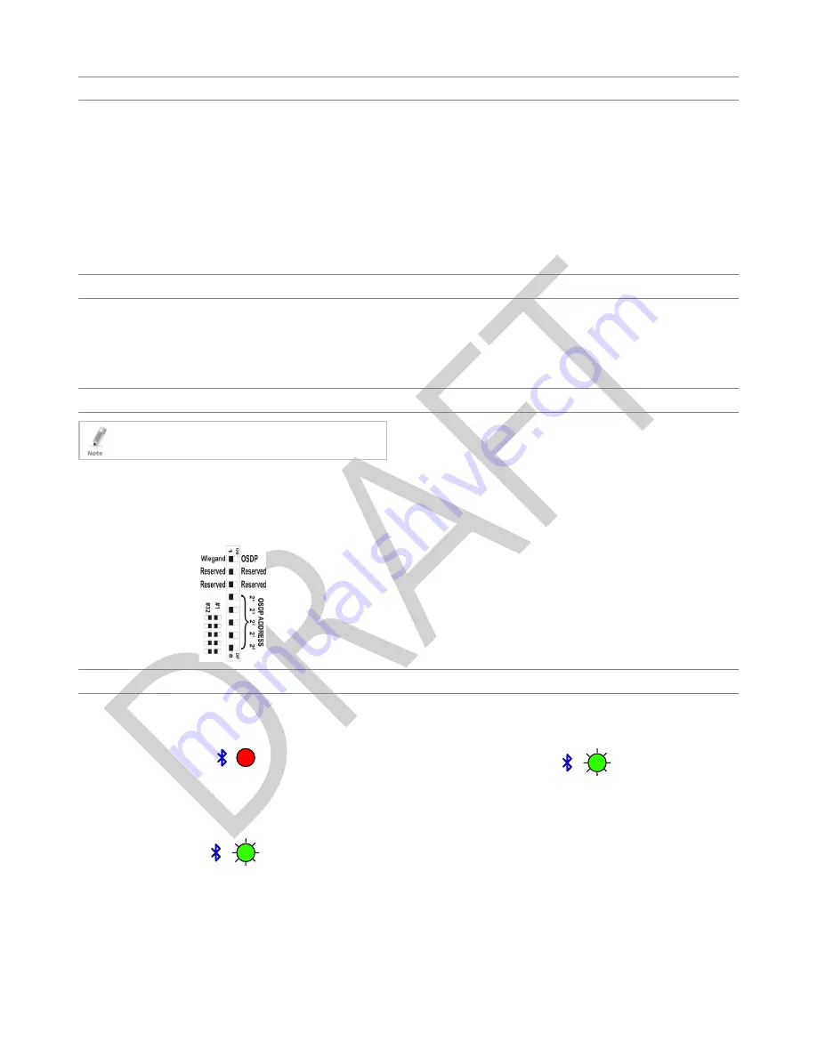
Figure 2 shows the DIP switch settings, which are described below.
Figure 2: DIP Switch Settings
DIP Switch 1
This switch is used to select the reader output (Wiegand or OSDP):
Off = Wiegand
On = OSDP
DIP Switch 2
This switch is reserved for future use.
DIP Switch 3
This switch is reserved for future use.
DIP Switches 4 to 8
These switches set the address of the reader for OSDP protocol.
DIP Switch 4 is MSB and DIP Switch 8 is LSB. The address is the DIP
switch state +1.
Examples:
All the DIP switches in Off position, address = 1
All the DIP switches in On position, address = 32
7.
LEDs Operation
7.1
Standby Mode
Once the reader powers on (or resets), the reader enters Standby
Mode. The left LED is blue and the right LED is red.
7.2
Card Read
When the reader reads a contactless card or NFC ID read, the right LED
flashes green and the unit beeps once. The data is transferred to the
host via Wiegand.
7.3
NFC ID Read
When the reader reads an NFC ID, the right LED flashes green and the
unit beeps twice. The ID is transferred to the host via Wiegand.
red
blue
green
blue
green
blue


