


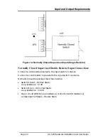


AC-525 Panel Set-Up
3.5
Power Supply
The following diagram illustrates the wiring between the AC/AC adaptor
and the AC525. It is recommended to add a 12VDC lead acid backup
battery if the main power supply fails.
Backup battery must be used if implementing Figure 4 and Figure 5
(connecting lock device to battery power, when more than 1A of current
is required).
For further information refer to the Outputs section on page 25.
Figure 6: Wiring the Power Supply
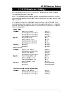
3.6
Reader
Proximity and keypad readers are supplied with a limited cable. The color
of the cable cover represents the cable’s function.
Note:
When extending the cable distance, be careful with the
color of the cable cover.
Refer to the reader specifications for the maximum cable length (typically
150m with an 18 AWG cable).
AC-525 Hardware Installation and User Guide
Page 15


