


AC-525 Panel Set-Up
3.2
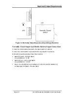
Inputs Wiring – Non-Supervised Inputs
I/O BOARD
J3
JP6
READER1
JP2
JP4
READER2
JP9
JP10
LED1
LED2
LED1
A
LED2
A
LED6
LED5
LED3LED4LED8
IN
(-
)
N.
C
N.
O
C
O
M
IN
(-
)
N.
C
N
.O
C
O
M
IN
(-
)
N.
C
N.
O
CO
M
IN
(-)
N.
C
N.
O
COM
+1
2
(-)
D
0
D
1
G
.L
E
D
T
A
M
P
+1
2
(-
)
D
0
D
1
G
.L
E
D
T
A
M
P
(+) (-)
L2 L1
RS485
VBAT
+12
(-)
~
~
16VAC
MD-14
IN
1
IN
1
A
IN
2
IN
2
A
OUT 1
OU
T 1A
OU
T 2
OU
T 2A
JP1
JP3
Door Monitor
Switch (N.C.)
F3
Release to Exit
(N.O.)
General Purpose
Input Switch (N.O)
Tamper Switch
(N.C.)
Figure 3: Inputs Wiring – Non-supervised Inputs
3.3
Inputs Wiring – Supervised Inputs
When wiring the AC-525 for supervised inputs, resistors should be placed
on the input switch and not on the terminal block.
For further details refer to Input and Output Requirements on page 18.
3.4
Outputs Wiring
The following diagram illustrates wiring for two main types of 12VDC
electrical release mechanisms. Other electrical devices can be switched
using the voltage free relay contacts.
AC-525 Hardware Installation and User Guide
Page 12


