AC-215x-B Series
2-Reader Networked Access Control Panel
Hardware Installation Manual and User Guide
Models:
AC-215-Bx AC-215-DIN AC-215IP-Bx AC-215IP-DIN
Page 1: ...AC 215x B Series 2 Reader Networked Access Control Panel Hardware Installation Manual and User Guide Models AC 215 Bx AC 215 DIN AC 215IP Bx AC 215IP DIN ...
Page 2: ...al property rights covering the subject matter in this manual TEXTS IMAGES AND ILLUSTRATIONS INCLUDING THEIR ARRANGEMENT IN THIS DOCUMENT ARE SUBJECT TO THE PROTECTION OF COPYRIGHT LAWS AND OTHER LEGAL RIGHTS WORLDWIDE THEIR USE REPRODUCTION AND TRANSMITTAL TO THIRD PARTIES WITHOUT EXPRESS WRITTEN PERMISSION MAY RESULT IN LEGAL PROCEEDINGS The furnishing of this manual to any party does not give t...
Page 3: ...unications 18 3 6 Reader 19 4 Input and Output Connections 20 4 1 Input Types 20 4 1 1 Normally Open Input Connection 20 4 1 2 Normally Closed Input Connection 21 4 1 3 Normally Open Supervised Single Resistor Input Connection 22 4 1 4 Normally Open Supervised Double Resistor Input Connection 22 4 1 5 Normally Closed Supervised Single Resistor Input Connection 23 4 1 6 Normally Closed Supervised D...
Page 4: ...4 Access Control Panel Addressing 29 6 Communications 31 6 1 Serial Network Connection 31 6 1 1 RS 232 Connection to the Computer 31 6 1 2 RS 485 Connection to the Computer 32 6 1 3 Daisy Chaining 33 6 2 TCP IP Network Connection 34 6 2 1 LAN and WAN Requirements 34 A Declaration of Conformity 36 B Radio Equipment Directive RED 37 C RoHS Directive 38 D Limited Warranty 39 ...
Page 5: ...losed Input Connection 21 Figure 12 Normally Open Supervised Input Single Resistor Connection 22 Figure 13 Normally Open Supervised Input Double Resistor Connection 23 Figure 14 Normally Closed Supervised Input Single Resistor Connection 23 Figure 15 Normally Closed Supervised Input Double Resistor Connection 24 Figure 16 DIP Switches 27 Figure 17 RS 232 Panel Connection to PC 31 Figure 18 RS 485 ...
Page 6: ...List of Tables Table 1 Description of AC 215x B Panels 8 Table 2 AxTraxNG Capabilities 9 Table 3 DIP Switches and Their Functions 27 Table 4 Switch Baud Rates 28 Table 5 Possible Hardware Settings 28 Table 6 Available Panel Addresses 29 Table 7 RS 232 Connection 32 ...
Page 7: ...the system with the maximum number of functions including future options Therefore not all functions described in this manual may be available in the specific system and or product configuration you purchased Incorrect operation or installation or failure of the user to effectively maintain the system relieves the manufacturer and seller from all or any responsibility for consequent noncompliance ...
Page 8: ...ed in ME 1015 with Type I plug power cable TCP IP connection AC 215IP BB Installed in ME 1015 with Type G plug power cable TCP IP connection AC 215IP BE Installed in ME 1015 with Type F plug power cable TCP IP connection AC 215IP BU Installed in ME 1015 with Type B plug power cable TCP IP connection AC 215IP DIN PCBA only with wall DIN rail mounting base TCP IP connection The IP models also includ...
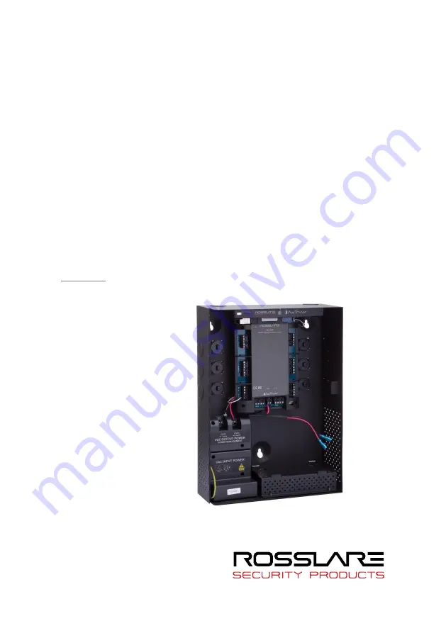
Page 9: ...id battery of up 12 V and 7 Ah and an intelligent light bar that provides enclosure lighting an enclosure tamper sensor and a power status LED indicator Figure 1 shows the general layout of the AC 215x panel Figure 1 AC 215x Panel 1 1 AxTraxNG The AxTraxNG software system is designed to set up manage and supervise all aspects of an access control panel network Table 2 presents the AxTraxNG softwar...
Page 10: ... permissions The system includes tools for database backup input and export of previous configurations and automatic backing up on a periodic basis 1 1 2 Configurable Links The system s configurable links model makes it possible to trigger any chosen output automatically or report a configurable alarm based on a selected input This allows easy integration with related access systems such as intrud...
Page 11: ...Tamper Input Visual Indicators 11 LEDs for outputs and communication status Audio Sounder output for use with compatible speakers provide chime bell and siren signals Battery Standby Time 3 hours with a 12 V 7 Ah lead acid battery Communication Characteristics RS 485 RS 232 RS 485 or optional RS 232 RS 485 connection by terminal block or MD 14U connector RS 232 connection by terminal block RS 232 ...
Page 12: ...ics Power Management Board PM 10 Input Power 15 VDC 4 A to the power management board Output Power Two PTC fused outputs each provides 13 8 VDC 2 A One output for controller and readers One output for locks Battery Charger 13 8 VDC 300 mA for 12VDC 7Ah Lead Acid Battery Speaker 0 5 Watt 8 Ohm Light Bar 0 3 Watt for LED light Environmental Characteristics Operating Temperature Range 0 C to 49 C 32 ...
Page 13: ...panels connect together in a network and are controlled by a central server computer running the AxTraxNG software system Figure 2 shows an example setup for a network of AC 215x access control panels Figure 2 Sample AC 215x Configuration The use of bushings is required for any conductors leaving the enclosure through the provided openings ...
Page 14: ...presents a detailed view of the non supervised inputs and their connection options Figure 3 Inputs Wiring Non supervised Inputs 3 2 Inputs Wiring Supervised Inputs When wiring the AC 215x for supervised inputs resistors should be placed on the input switch and not on the terminal block For further details see Chapter 4 ...
Page 15: ...stallation Manual 15 3 3 Outputs Wiring Figure 4 and Figure 5 illustrate wiring for two main types of 12 VDC electrical release mechanisms Other electrical devices can be switched using the voltage free relay contacts Figure 4 Door Lock Failed Close ...
Page 16: ...AC 215x Panel Setup 16 AC 215x B Series Hardware Installation Manual Figure 5 Door Lock Failed Open ...
Page 17: ...the connection polarity is correct to and to Connect the power to the input power terminals of the control panel It is recommended to add a 12 VDC lead acid backup battery requires the ME 1015 Power Management Enclosure to have uninterrupted operation in case main power supply fails A 12 V 7 AH battery provides 3 hours of backup operation Figure 6 Wiring Between PM 10 and AC 215x B ...
Page 18: ...18 AC 215x B Series Hardware Installation Manual 3 5 AC 215x B Wiring Communications Figure 7 presents a detailed view of the access control panel with all it wiring communications Figure 7 AC 215x B Wiring Communications ...
Page 19: ...aders are supplied with a limited cable length When extending the wire make sure to match the conductors to the correct terminals on the AC 215x panel Figure 8 Refer to the reader specifications for the maximum cable length typically 150 m with an 18 AWG cable Figure 8 Reader Wiring ...
Page 20: ...ised inputs Configure each input separately via the AxTraxNG system Non supervised inputs have two states Normal State Abnormal State Supervised inputs have three states Normal State Abnormal State Trouble State The Trouble state is caused by either tampering with the input circuit or by faulty hardware installation Once configured as supervised input add a resistor of 2 2 kΩ of 8 2kΩ or both on t...
Page 21: ...igure 9 Normally Open Input Connection 4 1 2 Normally Closed Input Connection Normally Closed Input has two states Switch Closed Normal State Loop resistance 0 short circuit Switch Open Abnormal State Loop resistance Infinite open circuit Figure 10 Normally Closed Input Connection ...
Page 22: ...ss input terminals Trouble State Loop resistance Infinite open circuit Figure 11 Normally Open Supervised Input Single Resistor Connection 4 1 4 Normally Open Supervised Double Resistor Input Connection Connect a 2 2 kΩ resistor in series to the input switch contacts Connect an 8 2 kΩ resistor parallel to the input switch contacts Normally Open Supervised Input has 3 states Switch Open Normal Stat...
Page 23: ... Input Connection Connect a 2 2 kΩ resistor in series to the input switch contacts Normally Closed Supervised Input has 3 states Switch Closed Normal State Loop resistance 2 2 kΩ Switch Open Abnormal State Loop resistance Infinite open circuit Short circuit across input terminals Trouble State Loop resistance 0 short circuit Figure 13 Normally Closed Supervised Input Single Resistor Connection ...
Page 24: ...stance 10 4 kΩ Open circuit Infinite loop resistance or short circuit 0 resistance across input terminals Trouble State Figure 14 Normally Closed Supervised Input Double Resistor Connection 4 2 Inputs Description 4 2 1 Request to Exit Button REX Input Use the REX input to open a door directly Typically the REX input is connected to a Normally Open push button that is located inside the premises Th...
Page 25: ... be used for various functions The following should be defined Single door controller Door 1 IN2 Door 1 INA Double door controller No general purpose inputs available General purpose inputs are suitable for most uses For example they might be used to detect tampering to activate alarm sensors or for monitoring power supply failure 4 3 Outputs Rosslare Security recommends the use of suppression dio...
Page 26: ...r 1 Reader 1 IN OUT Door 1 Reader 2 OUT IN Double door controller Door 1 Reader 1 IN OUT Door 2 Reader 2 IN OUT Use the AxTraxNG software to set the readers for IN or OUT use and to set the data transmission format for each reader The reader s tamper output connects to the access control panel s Reader Tamper input If the reader is interfered with an alarm can be generated The panel s Reader G LED...
Page 27: ...or This also affects the number of doors controlled by the panel 4 The access control panel s RS 485 network address 5 6 7 8 Power down the access control panel before changing the DIP switch settings After changes have been made restart the panel The new settings are automatically defined after power up In general the up position is ON and the down position is OFF as demonstrated in Figure 15 Fig...
Page 28: ...cess control panel setting is for two readers per each door OFF Defines using two readers for each door Panel controls one door ON Defines using one reader for each door Panel controls two doors Select the appropriate DIP switch setting to operate the panel as either a single door a double door or four doors see Section 5 3 Access control panels configured as either single door or double door cont...
Page 29: ...ccess control panel internal network address The default access control panel address is 1 For successful communications the DIP switch must match the address set in the AxTraxNG software Table 6 displays the 32 address settings available Table 6 Available Panel Addresses Address Switch 4 Switch 5 Switch 6 Switch 7 Switch 8 1 OFF OFF OFF OFF OFF 2 OFF OFF OFF OFF ON 3 OFF OFF OFF ON OFF 4 OFF OFF ...
Page 30: ...itch 7 Switch 8 18 ON OFF OFF OFF ON 19 ON OFF OFF ON OFF 20 ON OFF OFF ON ON 21 ON OFF ON OFF OFF 22 ON OFF ON OFF ON 23 ON OFF ON ON OFF 24 ON OFF ON ON ON 25 ON ON OFF OFF OFF 26 ON ON OFF OFF ON 27 ON ON OFF ON OFF 28 ON ON OFF ON ON 29 ON ON ON OFF OFF 30 ON ON ON OFF ON 31 ON ON ON ON OFF 32 ON ON ON ON ON ...
Page 31: ...Network RS 232 or RS 485 Modem Network TCP IP Network 6 1 Serial Network Connection The computer serial port controlling the access control panel is set from within the AxTraxNG software The default bitrate is 9600 bps for direct connection to the computer When using an RS 232 connector only one access control panel can be linked to each communication port on the computer Use an RS 485 connection ...
Page 32: ... panels can be linked together and connected to a single communication port on the computer Figure 17 Figure 17 RS 485 Panel Connection to PC Use the RS 485 interface for situations where there are multiple controllers connected The serial port used to control the access control panel is assigned within the AxTraxNG software The AC 215x B supports the 2 wire RS 485 interface which can significantl...
Page 33: ...The first panel is connected directly to the server using an MD 14U converter while the second panel connects to the first panel Additional panels are connected in the same way one after another The server identifies each panel on the RS 485 network by its address At each end of the data line both where the panel connects to the computer and on the last panel in the network a termination resistor ...
Page 34: ...ked panels can be connected via an RS 485 bus which means that one IP port can support up to 32 AC 215x B panels Figure 19 Figure 19 Connecting Multiple Access Control Panels to AC 215IP To connect to a TCP IP network using AC 215 non IP models add Rosslare s MD N32 TCP IP to RS 232 gateway converter For more information on operating an MD N32 refer to the MD N32 User Manual 6 2 1 LAN and WAN Requ...
Page 35: ...el by TCP IP connection for the first time the AxTraxNG software must configure the device Settings then remain stored in non volatile memory on the device see the AxTraxNG Software Manual When using an MD N32 for a single panel either an RS 232 cable or Rosslare s MD 14U RS 485 to RS 232 converter can be used To connect an MD N32 to more than one panel up to 32 panels Rosslare s MD 14U RS 485 to ...
Page 36: ... to provide reasonable protection against harmful interference in a residential installation This equipment generates uses and can radiate radio frequency energy and if not installed and used in accordance with the instructions may cause harmful interference to radio communications However there is no guarantee that interference will not occur in a particular installation If this equipment does ca...
Page 37: ...tion Manual 37 B Radio Equipment Directive RED Under our sole responsibility that the following labeled AC 215 Bx AC 215 DIN AC 215IP Bx and AC 215IP DIN are tested to conform to the EU Radio Equipment Directive RED 2014 53 EU in electrical and electronic equipment ...
Page 38: ...anual C RoHS Directive Under our sole responsibility that the following labeled AC 215 Bx AC 215 DIN AC 215IP Bx and AC 215IP DIN are tested to conform to the Restriction of Hazardous Substances RoHS directive 2011 65 EU in electrical and electronic equipment ...
Page 39: ...9 D Limited Warranty The full ROSSLARE Limited Warranty Statement is available in the Quick Links section on the ROSSLARE website at www rosslaresecurity com Rosslare considers any use of this product as agreement to the Warranty Terms even if you do not review them ...
Page 40: ...resecurity com Europe Rosslare Israel Ltd 22 Ha Melacha St P O B 11407 Rosh HaAyin Israel Tel 972 3 938 6838 Fax 972 3 938 6830 support eu rosslaresecurity com Latin America Rosslare Latin America Buenos Aires Argentina Tel 54 11 4001 3104 support la rosslaresecurity com China Rosslare Electronics Shenzhen Ltd Shenzhen China Tel 86 755 8610 6842 Fax 86 755 8610 6101 support cn rosslaresecurity com...