Rosslare AC-115 Software Manual Download Page 36

Set Up Your First Door 

AC-115 Software Installation and User’s Guide 

Page 35 


3.3


Enable your First Door 

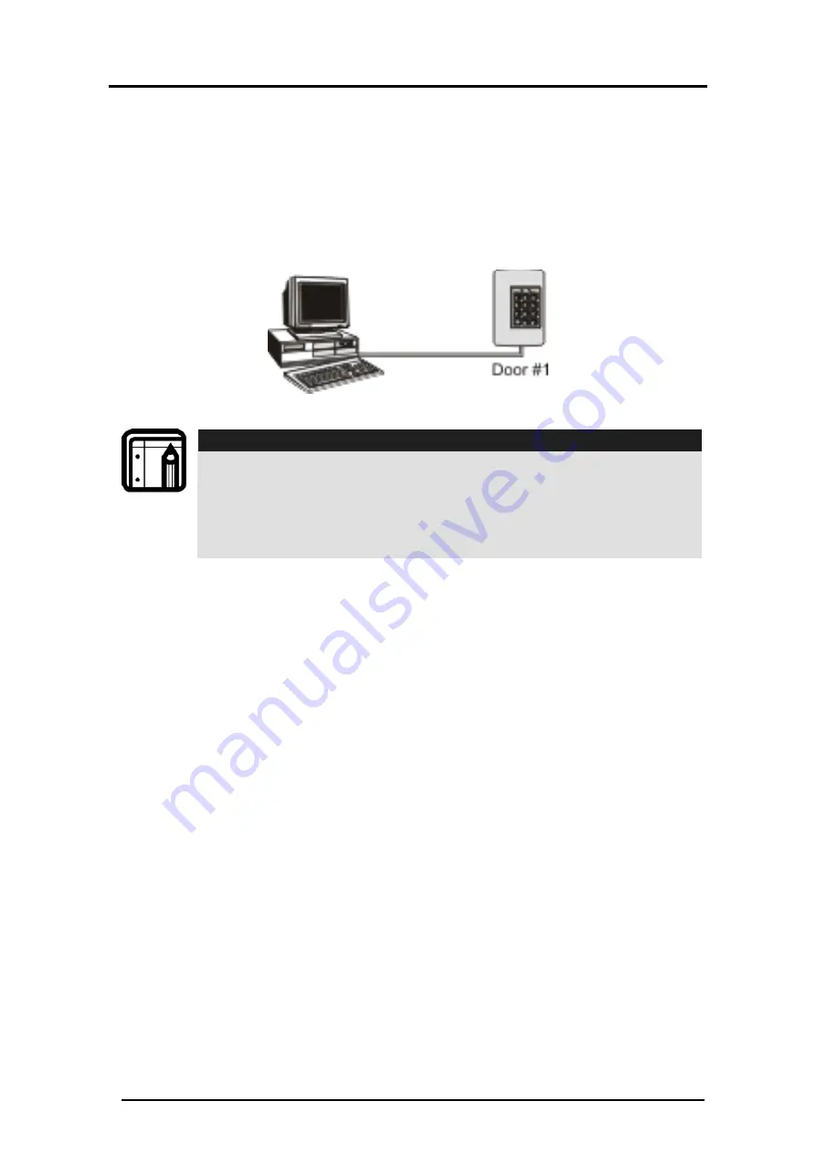
Install your First Door 
In this section, you’ll learn how to setup your first door. You 

need the following hardware setup in order to complete this 

section: 


Figure 39: Door Enable 


Note: 

The AC-115 in this setup has its Door Number set to #1. A 
new AC-115 from the factory is set to Door Number one 
by default. If you are not sure what your AC-115 
hardware’s Door Number is, then follow the instructions 
on page 16 to set your AC-115’s Door Number to #1. 

 
To install your first door, you first enter the Doors window. From 

the Doors Menu, you can install and uninstall any of the eight 

doors in the network. To install Door #1, you need to see the 

Door Properties for Door #1. 

Get the Door Properties for Door #1  
Follow the instructions below to view the Door Properties for 

Door #1: 

Summary of Contents for AC-115

Page 1: ...AC 115 Compact Networked Single Door Controller Software Manual March 2008 ...

Page 2: ......

Page 3: ...erial Port COM Port Configuration 18 2 5 Set Up Your Preferred Language 20 2 6 Configure the Operators 22 2 7 Add an Operator 23 2 8 Remove an Operator 24 2 9 Operator Properties 24 2 10 PC Software Database Status 29 3 Set Up Your First Door 31 3 1 Modes of Operation 32 3 2 Download and Upload 34 3 3 Enable your First Door 35 3 4 Download Settings to the Hardware 40 3 5 Test Your Network for the ...

Page 4: ... 60 5 2 Occasions to Upload the Event History 61 5 3 Upload Event History Manually 62 5 4 Upload Event History Automatically 63 5 5 Introduction to Reports 64 5 6 Report Setup 65 5 7 Generate Movement Reports 66 5 8 Generate Attendance Reports 72 5 9 Generate Door Reports 74 5 10 Generate Interactive Reports 79 Appendix A Language Setup 84 Appendix B Using the MD 08 87 Appendix C Limited Warranty ...

Page 5: ...s membrane keypad However there are many features that can only be set by the AC 115 PC software The PC software must be used when more than one AC 115 is joined in a network of doors This manual explains how to install and use the AC 115 PC software with one or more doors This section describes this manual and how to choose the right operating system and the necessary hardware required to use you...

Page 6: ...is manual can also be found on the AC 115 PC Software installation CD 1 2 Select the Right Operating System The AC 115 software functions in English on any PC using the following Operating Systems Windows 95 98 ME Windows NT 2000 Windows XP 2003 server There are however some special considerations to take into account when using the AC 115 multi language support feature Select the Right Operating ...

Page 7: ...ove for your language see Appendix A 1 3 Select the Right PC Hardware Your PC Hardware must be capable of handling any of the below Operating Systems Windows 95 98 ME Windows NT 2000 Windows XP 2003 server To install the software you need a minimum of 300MB available on your Hard Disk Your PC also requires an available Serial Port 9 PIN Connector 1 4 Install the AC 115 PC Software The installation...

Page 8: ... installation To cancel click Cancel to quit the AC 115 PC software installer 4 Choose the Destination Location The installer prompts you to enter the destination location for the installation This is where the AC 115 PC software is stored on your hard disk Figure 2 Setup Destination 5 Click Next to accept the default installation location and continue with the installation ...

Page 9: ...ew installation location click Next to continue with the installation 6 Select a program folder Figure 3 Program Folder Select This window determines where the AC 115 PC software will appear in your PC s Windows Start menu 7 Click Next to accept the default Start menu location and continue with the software installation 8 Finalize your installation ...

Page 10: ...ered Installation can now begin This is your final chance to cancel the installation Click Cancel if you wish to cancel the installation or click Next to install the AC 115 PC software 10 Installation Complete Figure 5 Setup Complete If you see this screen you have successfully installed the software Click Finish to Exit the installer ...

Page 11: ...AC 115 hardware to a PC and check to make sure that the communication between the AC 115 and the PC is really working To do this you will learn how to login to the software how to set up your serial port COM port and you will get a brief introduction to the software s Main Window The topics in this chapter are Connect the AC 115 to your PC Start the Software and Log In Introduction to the Main Win...

Page 12: ...wer supply It is assumed that you have already installed the AC 115 hardware This section describes how to wire the AC 115 to the PC To do this you need an RS485 to RS232 converter cable Rosslare Model Number MD 14 This cable can be ordered from your Rosslare Security products supplier A picture of the MD 14 has been provided below to help you identify the cable Figure 6 RS 232 to RS 485 Connectio...

Page 13: ...u receive a new MD 14 the RS485 connector should look like the following Figure 7 New MD 14 Cut the connector off and remove about 3 inches 7 cm of cable shielding and strip the ends of the four wires about a quarter of an inch 5 mm Figure 8 Modified MD 14 Connect the MD 14 to the AC 115 and your PC The wiring diagram below demonstrates how to attach the MD 14 to the AC 115 Figure 9 MD 14 to AC 11...

Page 14: ... 14 to the AC 115 and to your PC serial port COM Port Connect More than One AC 115 to the PC The diagram below shows how to connect more than one AC 115 to the PC in order to build a multi door AC 115 network Note that you need only one MD 14 for the whole network Once wired and powered you must set the Door Numbers of the AC 115 s in the network Figure 10 Multiple AC 115 to PC ...

Page 15: ...5 controller and not from the PC This is called local programming Local programming is covered in extensive detail in the AC 115 Hardware Installation and Users Guide First a quick introduction of the AC 115 local programming interface Figure 11 AC 115 Keypad There are two status LED s on the AC 115 n This DOOR LED is used to assist navigation through the local programming menu o This MODE LED ind...

Page 16: ... for confirmation If the Programming Code Is valid the Mode LED stops flashing 3 Press 61 to enter Menu 61 The Mode LED turns red 4 Enter the 2 digit Door Number between 01 and 08 This is the new door number The Mode LED turns orange 5 Press the key for 3 seconds to exit programming mode The Mode LED turns green You have now programmed the Door Number of an AC 115 door controller This must be done...

Page 17: ...oftware Operators of the software can be assigned to have different access rights to the software Limits can be placed on which menus the user has access to You will lean more about setting user levels later To Log In 1 Enter the Name admin and Password admin 2 Click OK You have now successfully logged into the software as the operator named admin The software now attempts to connect to the AC 115...

Page 18: ...line mode later 2 3 Introduction to the Main Window Now that you have successfully logged into the PC software you are ready to make sure that your AC 115 software is communicating correctly with the AC 115 In this section you will learn how to setup your Serial Port COM Port and make sure that your AC 115 s are communicating After logging in the software s main window is displayed depending on th...

Page 19: ...menus and commands Click on each icon to transition to the desired section Online Activates a screen for Online messages Employees Manages the employee functions Doors All functions related to doors Setting System settings Reports Configure and generate reports Download Activates a screen for download of all data from the PC to the Access control Exit Exit the system 2 4 Serial Port COM Port Confi...

Page 20: ...and User s Guide Page 19 1 Click Setting on the tool bar The Settings Window displays Figure 17 Settings Window 2 Click the Options The Options window is displayed Figure 18 Settings Options 3 Click Communications The following Communications Setup window pops up ...

Page 21: ...tab to test the connection of each of the installed doors in the network 7 When you have completed entering your communication settings click OK The software attempts to connect to the equipment using the new settings 2 5 Set Up Your Preferred Language The AC 115 currently supports the following languages Chinese Simplified Chinese Traditional English Estonian French German Hebrew Italian Russian ...

Page 22: ... NT If you are using Windows 2000 and above you do not have to purchase the Russian version as Windows 2000 and above already have multi language support You must still configure Windows 2000 and above to display the characters correctly and to function with your keyboard For more information about setting up Windows 2000 and above for your language see Appendix A Figure 20 Language Settings Acces...

Page 23: ...anges to the selected language Below are examples of the AC 115 PC software in Italian and Russian Italian Russian 2 6 Configure the Operators The AC 115 PC software supports multiple users each with their own access rights to the various menus and options within those menus Adding removing and maintaining users and their access rights are accomplished from the Operators Window ...

Page 24: ... Figure 22 Operators Access 1 Click Setting on the tool bar The Setting window is displayed 2 Click the Options tab 3 Click Operators The Operators Configuration page is displayed Figure 23 Operators Configuration 2 7 Add an Operator 1 Click Add The Add New Operator window is displayed ...

Page 25: ...he new operator 2 8 Remove an Operator 1 Click Remove The Remove Operator window is displayed Figure 25 Remove Operator 2 Click Yes to continue removing the operator Click No to stop removal 2 9 Operator Properties Each tab contains a logical group of privileges available to the operator At any time you can complete the operator configuration by clicking OK You can cancel at anytime by clicking Ca...

Page 26: ... tab provides for entering a unique password for each new operator The description can be anything but is limited to 25 characters 1 Enter a password for the new operator 2 Enter a description of the operator Menus Figure 27 Operator Properties Menu Access Each checkbox represents access if checked or denial if un checked to view menus ...

Page 27: ...d to view Employees Figure 28 Operator Properties Employees Each checkbox represents the privilege to add remove and edit an employee item Select each type of employee access this operator has Doors Figure 29 Operator Properties Doors When this checkbox is selected the operator has the ability to change the door configuration ...

Page 28: ...rator Setting Figure 30 Operator Properties Settings These checkboxes allow the operator to change settings and options Select the Change Settings and Options if applicable to this operator Options Figure 31 Operator Properties Options These options allow the operator access to communications and language settings operator settings and the data base ...

Page 29: ...s Figure 32 Operator Properties Operators These options allow the operator to add and remove operators from the system If checked the operator can also edit operator information Select the appropriate options for this operator Reports Figure 33 Operator Properties Reports The report options allow the operator to configure and generate reports ...

Page 30: ...ware Database Status Periodically the AC 115 Access Control Network system prompts you to compact its database This procedure makes sure that your database is kept in its best condition allowing it to be accessed faster If your system has heavy traffic the system prompts you to compact the database more often Figure 34 Database Access Click Data Base The Database Location window is displayed ...

Page 31: ...hether or not the database needs to be compacted Click Compact to start the process Automatic Back Up None Day Week Month Year Day 1 6 days Week 1 3 weeks Month 1 11 months Year 1 3 years Jobs Open External Select All or Configuration and then click Import Copy Current Select All or Configuration and then click Export Open New Click New to open a new database Close Click Close to close the databas...

Page 32: ...rn how to program all of the AC 115 s settings This chapter will walk you through the whole setup process from beginning to end Along the way you will learn how to use every feature of the AC 115 The topics in this chapter are Modes of Operation Download and Upload Enable your First Door Download Settings to the Hardware Test Your Network for the First Time Set up the System Codes Set up Activitie...

Page 33: ...le 2 All the doors marked as installed are functioning and communicating properly 3 At least one door is marked as installed If conditions 1 and 3 are not met the software does not enter Online mode it stays in Offline Mode If the above conditions are met the software enters Online Mode Offline Mode In Offline Mode a user can change almost all of the door and user settings However these settings d...

Page 34: ...eration is as simple as clicking the File Menu and clicking on the Work Offline menu item See below Figure 36 Offline Indicator A check mark next to Work Offline indicates that the software is in Offline Mode If you are currently Offline un checking Work Offline commands the system to attempt to enter Online Mode If you are currently Online un checking Work Offline commands the system to exit Onli...

Page 35: ...s are downloaded from the PC to the AC 115 hardware in the AC 115 network If settings are changed the software stores these changes If the user makes changes to the settings and exits the software without downloading the settings to the AC 115 hardware in the AC 115 network the software still saves the changed settings This allows the user to download the settings to the AC 115 network later Uploa...

Page 36: ...et to 1 A new AC 115 from the factory is set to Door Number one by default If you are not sure what your AC 115 hardware s Door Number is then follow the instructions on page 16 to set your AC 115 s Door Number to 1 To install your first door you first enter the Doors window From the Doors Menu you can install and uninstall any of the eight doors in the network To install Door 1 you need to see th...

Page 37: ... 1 Click Doors on the tool bar The Doors Window is displayed 2 Double click on the row marked as Door 1 to get the Door Properties for Door 1 Set the Door Properties for Door 1 Below is the Door Properties window for Door 1 Figure 41 Single Door Properties 1 Select the Door Installed checkbox to Install Door 1 ...

Page 38: ...re 42 Single Door Configuration 1 Configure the operation settings for the Lock Strike Relay Normally Open Normally Close Strike Time 2 Configure the operation settings for the Auxiliary Relay Normally Open Normally Close Toggle Aux Time 3 Configure which outputs are activated when the REX switch is pushed Strike or Aux 4 Configure which events cause the Chime Alert to sound e g when the door is o...

Page 39: ...or Ajar Event A door ajar event occurs when a door is left open longer then the door ajar time Forced Door Event If a door is opened without a valid code being entered then the forced door event will be activated Tamper Event If the AC 115 bezel is removed or if the AC 115 loses its connection with a reader a tamper event will be activated Duress Event If a duress code is entered then the duress e...

Page 40: ... Added Example Notice that the status of each door installed is now Changed This means that there are settings that have been changed on the PC software that have not been sent to the AC 115 door network Changes made to settings in the software do not update the AC 115 network immediately Changed settings are only updated to the controllers when the download procedure is initiated In the next sect...

Page 41: ... the controllers in the network Figure 46 Download Progress Window When the PC software is in Offline Mode Download on the toolbar is grayed out To enable Downloading the PC software must first be placed into Online Mode When installing a new Door the first download takes longer as all the settings in the new Door are to be updated Downloading to existing doors is very fast as only the changed set...

Page 42: ...he Employee Codes at each of the In Out Readers attached to the controllers in the network Note There are two conditions that need to be met before you can start testing All the doors you want to test must have Online Enabled active in their door properties If Online Enabled is not active in a door then the status of that door will not appear in the Online Window You must be in Online Mode in orde...

Page 43: ...the controller over the 26 Bit Wiegand Reader s output Below is an example of what your Online Window should look like after you have created a few events by activating all the readers in your network Figure 48 Devices Online In this example there are 4 controllers in the AC 115 network All the readers were tested for each of the controllers on the network If all the readers show up on your list t...

Page 44: ...s done in the Systems Code tab within the Settings Toolbar Figure 49 Configure System Codes 1 Click Setting on the tool bar The Setting window is displayed 2 Click the System Codes tab From this window you can set all listed codes Look at the row with the description Programming Code Notice the keyboard icon and the type being PIN The icon indicates that this Programming Code is active and it is a...

Page 45: ...d ID Code 6 Click Add and continue on the next page You will see the Code type selection window shown below There are three methods to enter the code Figure 51 Select Code Type Prox Card o The Door checkbox adds a code using a reader that is attached to any AC 115 hardware in the network o The MD 08 checkbox adds a code using any 26 Bit Wiegand compatible reader attached to the PC using the MD 08 ...

Page 46: ...downloaded to the controller network System codes are global this means that all the controllers in the network have the same system code settings 3 7 Set up Activities and Times Zones By default holders of Valid Employee Codes are given 24 hours access when the controllers are in Normal Mode Using the PC software access to set up access times during Normal Mode can be programmed by setting up sch...

Page 47: ...lation and User s Guide Page 46 Figure 52 Configure Time Zones 1 Click Setting on the tool bar The Setting window is displayed The Time Zones tab is the default tab From this window you can set all Activities 2 Double click the row marked Number 1 ...

Page 48: ...box to enable this Activity If you do not enable the Activity it is not be available when applying Activities to Employee Codes Select the Time Zones when access will be granted for performing this activity for each day of the week 4 The Time Zone marked Holiday is a special time zone that is only in effect on days that are marked in the system as Holiday Dates This is discussed in Set up the Holi...

Page 49: ...Example As you can see setting up the Automatic Normal to Bypass Mode switching schedule is similar to setting up an Activity schedule 3 Click the Enable check box to enable this Activity If you do not enable the Activity it is not available when applying Activities to Employee Codes 4 Select the Time Zones when access is to be granted for performing this activity for each day of the week Note The...

Page 50: ...ones in each of the eight Activities and also have their own Automatic Normal Secure Mode switching Time Zones Figure 55 Holiday Setup 1 Click Setting on the tool bar The Setting window is displayed 2 Click on the Holidays tab 3 Double click on the row marked as Holiday 01 You will see the following window Figure 56 Holiday Properties 4 Click the Enable check box to enable this Holiday If you do n...

Page 51: ...trollers in the AC 115 network 3 10 Set up the System Date and Clock The AC 115 network can be synchronized with the PC date and time in the programming screen This can be an automated process which will be done upon every download Figure 57 Set Date and Clock 1 Click Setting on the tool bar The Setting window is displayed 2 Click the Clock tab 3 Click Set Clock update the clock 4 Check the Automa...

Page 52: ...oftware Installation and User s Guide Page 51 Figure 58 Clock Properties 5 Select to set the time in the network to the same time as your PC Clock or Set up a custom time that is different from your PC Clock 6 Select the correct date ...

Page 53: ...C database and then sent to the controllers in the network upon downloading In this chapter you will learn how to add and delete users and maintain current users by editing their settings The topics in this chapter are Add Employees Edit Employees Settings Delete Employees 4 1 Add Employees Managing Employee activities door rights codes and other information all take place from the Employee window...

Page 54: ... in the Details Tab setting up at the top The Employee s permitted entry time is done by assigning activities in the Time Zones tab Finally you must edit the Employee s door rights and the Lock Strike and Auxiliary Event Actions for each installed door in the system from within the Rights tab Add Employees General Settings 1 Enter Name Employee Number and the Department of the new employee 2 Inser...

Page 55: ...g a reader that is attached to any AC 115 hardware in the network The MD 08 checkbox adds a code using any 26 Bit Wiegand compatible reader attached to the PC using the MD 08 a 26 Bit Wiegand to RS232 Converter Accessory Purchased separately See Appendix B for more information on the MD 08 Pin Code adds a PIN code using the PC keyboard Select the method of entry of your preference make an entry wi...

Page 56: ...nter the number of hours this employee is expected to work in a day Start Time Enter the time the employee is expected to begin work This effects the late time calculation Stop Time Enter the time the employee is expected to complete work This effects the early leave calculation When the Overnight option is selected Start time is automatically set to 00 00 End time is automatically set to 23 59 Th...

Page 57: ...d 24 hour access or if they are constrained to any specific times preprogrammed activities Select 24 Hours to give the user 24 hour access to any of the doors that they have access to or Select Time Zones and then select the Activities that this user has been approved for Activities will only show here if you have setup and enabled them in the Settings window You can assign multiple Activities for...

Page 58: ...oors 1 and 4 both the Lock Strike and the Auxiliary are activated upon entry of a Valid Code When a valid code is entered at door 2 but the employee does not have access to it Events Door Opened and Auxiliary Opened do not occur and Event Action Door Not Opened occurs therefore this user has no access to door 2 For door 3 only the Lock Strike Output activation Event Action occurs when a valid code...

Page 59: ... confirm the changes Changes only take effect after the new settings have been downloaded to the controllers 4 3 Delete Employees Select the employee you wish to delete from the Employee window see the screen shot above and click Remove to delete the user A confirmation window appears click OK to confirm the removal of the user or click Cancel to cancel the removal of the user Note Changes take ef...

Page 60: ...urred at that controller Periodically the event history stored in the internal memory of the AC 115 controller must be uploaded to the PC using the AC 115 PC software In this chapter you will learn how to upload the AC 115 controllers event history to the PC and how to generate reports The topics in this chapter are Event History Definition Occasions to Upload the Event History Upload Event Histor...

Page 61: ...or Not Opened Secure Mode Inside Door Not Opened Time Zone Inside Unknown Code Passed Inside Unknown Code Passed Outside Strike Code Passed Inside Strike Code Passed Outside Strike Code Not Opened Secure Time Inside Door is Released Employee Code Passed Inside Door is Released Employee Code Passed Outside Door Opened By REX Secure Mode Bypass Mode Normal Mode Ajar Mode Started Ajar Mode Stopped Fo...

Page 62: ...of the reports In order to prevent Event Overflow each controller in your AC 115 must have its event history uploaded to the PC software s database periodically There are two methods to upload the event history from the AC 115 controllers in your network manual and automatic uploading Manual or Automatic Upload Note Manual Uploading has been designed for AC 115 networks that do not have a lot of e...

Page 63: ...y from all the AC 115 controllers in the network at the same time or you can specifically select the Door Numbers belonging to the AC 115 controllers that you wish to upload data from Figure 66 Upload History 1 Click Reports on the tool bar The Reports window is displayed Click Upload History Data Now The following window appears Figure 67 Door Selection for History Upload 2 Select All Doors if yo...

Page 64: ...ll the controllers or the controllers selected begins You have now manually uploaded the event history from the controllers in your AC 115 network 5 4 Upload Event History Automatically The AC 115 software Automatic Upload feature can be turned on from its Door Properties To reach controller door properties follow the example below Figure 68 Door Access 1 Click Doors on the tool bar The Doors wind...

Page 65: ... Software can generate four types of reports Movement Attendance Door and Interactive Reports In this section you learn about these reports and in the following sections you will learn how to generate each of them Movements Report The Movement Report shows all the Lock Strike Activation Events that occurred due to an entry of a valid employee code Movement Reports are available in two formats sort...

Page 66: ...es and door access rights Interactive Reports are available in two formats sorted by door number and sorted by employees The report sorted by door number enables you to clearly see who has rights to each of the doors in the network The report sorted by employees enables you to clearly see each employee s door rights 5 6 Report Setup Before you begin to generate reports there are a few settings tha...

Page 67: ...n the Details area you may enter details that you wish to appear below your name on the report 6 Click Add and select a jpg file to use as your logo 7 Finally you must check Show company properties at report in order to view the company information on your reports 8 When you have completed entering all the settings click Save located on the bottom right corner of the window 5 7 Generate Movement R...

Page 68: ... or a selected set of doors employees If you choose to select the doors to be included in the report then you must click on the check box beside each door you want to include in your report 5 Select production options an AC115 report or a log file 6 Select the date limits for the report 7 Select the sort order 8 When you have finished entering all the report settings click OK to generate the movem...

Page 69: ...r s Guide Page 68 Movement Reports Employee List by Door All Doors Figure 73 Employee List for All Doors Configuration Report Type Employee list by door Doors All doors Date 25 07 2006 to 01 09 2007 The following report is generated Figure 74 Movements Report by Door ...

Page 70: ...e 69 Movement Reports Employee List by Door Selected Doors Figure 75 Employee List for Selected Doors Configuration Report Type Employee list by door Doors Doors 2 and 4 only Date 25 07 2006 to 01 09 2007 The following report is generated Figure 76 Employee List for Selected Doors ...

Page 71: ...Guide Page 70 Movement Reports Doors List by Employee All Employees Figure 77 All Employees Movement Report Setup Report Type Doors list by employee Doors All employees Date 25 07 2006 to 01 09 2007 The following report is generated Figure 78 All Employees Movement Report ...

Page 72: ...1 Movement Reports Doors list by Employee Select Employees Figure 79 Selected Employees Movement Report Setup Report Type Doors list by employee Doors Selected employees Clod Nik Long Vean Nir Allen Stodd Aleks Troy Eli Date 25 07 2006 to 01 09 2007 The following report is generated ...

Page 73: ...Page 72 Figure 80 Selected Employees Movement Report 5 8 Generate Attendance Reports 1 Click Reports from the Toolbar Figure 81 Attendance Report Access 2 Click Attendance Report The Attendance Report Data Base Window is displayed Figure 82 Attendance Report Working Hours Setup ...

Page 74: ... Hours or Absence 4 Select the sorting order Employee Name Employee Number or Date 5 Select the date range for the report 6 Select All Employees or Selected Employees This report is configured to display Working Hours sorted by Employee Name for all Employees It is followed by a report based on Late Hours Figure 83 Attendance Report Working Hours ...

Page 75: ...ry Create Reports AC 115 Software Installation and User s Guide Page 74 Figure 84 Attendance Report Working Overnight Figure 85 Attendance Report Late Hours 5 9 Generate Door Reports 1 Click Reports on the tool bar ...

Page 76: ...The Reports window is displayed 2 Click Door Report The following Door Report window displays Figure 87 Door Events Report Screen 3 Select the events that you wish to see on the reports Figure 88 Select Door Event for Report 4 Select whether you want all doors to be included in the report or a selected set of doors ...

Page 77: ... you want to include in your report 5 Select the date limits for the report 6 When you have finished entering all the report settings click OK to generate the Door Report Some example Door Reports have been provided on the next few pages Door Report All Events All Doors Report Type All Events Doors All doors Date 25 07 2006 to 01 09 2007 The following report is generated Figure 89 Door events Repo...

Page 78: ...allation and User s Guide Page 77 Door Report Tamper Events All Doors Figure 90 Door Tamper Event Report Setup Report Type Tamper Events Doors All doors Date 25 12 2006 to 01 01 2007 The following report is generated Figure 91 Door Tamper Event Report ...

Page 79: ...and User s Guide Page 78 Door Report Auxiliary Events Door 2 and 4 Figure 92 Door Auxiliary Event Report Setup Report Type Auxiliary Events Doors Door 2 and 4 Date 25 07 2006 to 01 09 2007 The following report is generated Figure 93 Door Auxiliary Event Report ...

Page 80: ...All Doors Report Setup 3 Select how you want the reports to be sorted 4 Select whether you want all doors employees to be included in the report or a selected set of doors employees If you choose to select the doors to be included in the report then you must click on the check box beside each door you want to include in your report 5 When you have finished entering all the report settings click OK...

Page 81: ...Report Employee List by Door All Doors Report Type Employee list by door Doors All doors The following report is generated Figure 96 Interactive Door Report of Employees by Door Interactive Report Employee List by Door Selected Doors Figure 97 Interactive Report of Employees by Selected Door Setup ...

Page 82: ...ype Employee list by door Doors Doors 1 4 and 5 The following report is generated Figure 98 Interactive Report of Employees by Door Interactive Report Doors list by Employee All Employees Figure 99 Interactive Report of All Employees Setup Report Type Doors list by employee Doors All employees ...

Page 83: ...ware Installation and User s Guide Page 82 The following report is generated Figure 100 Interactive Report of All Employees Interactive Report Doors List by Employee Selected Employees Figure 101 Interactive Report for Selected Employees Setup ...

Page 84: ...15 Software Installation and User s Guide Page 83 Report Type Doors list by employee Doors Selected employees Clod Nik Ogange Len Stodd Aleks Tim Dom The following report is generated Figure 102 Interactive Report for Selected Employees ...

Page 85: ...ng how to change the language from English to Russian The same steps can be used to change languages to any of the available languages Step 1 Try to Change Languages within the AC 115 Software 1 Click Settings on the program tool bar 2 Click the tab marked Options 3 Click Language You should see the following if you are running the English version of Windows 2000 or above Figure 103 Available Lang...

Page 86: ... Step 2 Changing the Default Locale on Windows 2000 and Above 1 Open the Regional Options applications from your Windows control panel Figure 104 Language Settings Figure 105 Set the Local Region Assuming you want to see Russian text in the AC 115 PC software you must first select Cyrillic in the language settings for the system ...

Page 87: ... Cyrillic compatible locale from the drop down menu such as Azeri Serbian or Uzbek and then click OK 4 Select a Cyrillic compatible locale from the Your locale drop down menu such as Azeri Serbian or Uzbek 5 Click OK to confirm the Regional Options Settings You may be required to insert your Windows 2000 and above installation CD to install additional files and to restart your PC Repeat STEP 1 and...

Page 88: ...loyee and System Codes Instead you may program Employee and System Codes using a Reader attached to the MD 08 You could even pre program all the Employee and System Codes for a network in your office prior to departing to the site of the AC 115 network you are installing or maintaining There are three ways to attach 26 bit wiegand readers to the MD 08 Wiring a reader directly to the MD 08 s termin...

Page 89: ...ly to the MD 08 s Connector Input MD 08 Connector to Reader Readers are not provided with the MD 08 and must be purchased separately Installing Rosslare s MD 12W Prox Reader Module Directly into the MD 08 Figure 107 MD 12W to MD 08 The MD 12W is not provided with the MD 08 and must be purchased separately ...

Page 90: ...ng period following the delivery of the warranty claim Customer will not be required to return the failed product s All returned Product s as may be requested at ROSSLARE ENTERPRISES LTD AND OR SUBSIDIARY S sole discretion shall become the property of ROSSLARE ENTERPRISES LTD AND OR SUBSIDIARIES To exercise the warranty the user must contact Rosslare Enterprises Ltd to obtain an RMA number after w...

Page 91: ... maintenance or service of the Product Service life of the product is dependent upon the care it receives and the conditions under which it has to operate In no event shall Rosslare be liable for incidental or consequential damages Limited Warranty Terms THIS WARRANTY SETS FORTH THE FULL EXTENT OF ROSSLARE ENTERPRISES LTD AND IT S SUBSIDIARIES S WARRANTY THE TERMS OF THIS WARRANTY MAY NOT BE VARIE...

Page 92: ...om United States and Canada 1600 Hart Court Suite 103 Southlake TX USA 76092 Toll Free 1 866 632 1101 Local 1 817 305 0006 Fax 1 817 305 0069 E mail support na rosslaresecurity com Europe Global Technical Support Training Center HaMelecha 22 Rosh HaAyin Israel 48091 Tel 972 3 938 6838 Fax 972 3 938 6830 E mail support eu rosslaresecurity com South America Pringles 868 1640 Martinez Buenos Aires Ar...

Page 93: ......

Page 94: ...0706 0960226 00 www rosslaresecurity com ...

Reviews: