background image

SEA-8803 User Manual (Iss. 02)

Configuration • 3–3

Monitoring Features

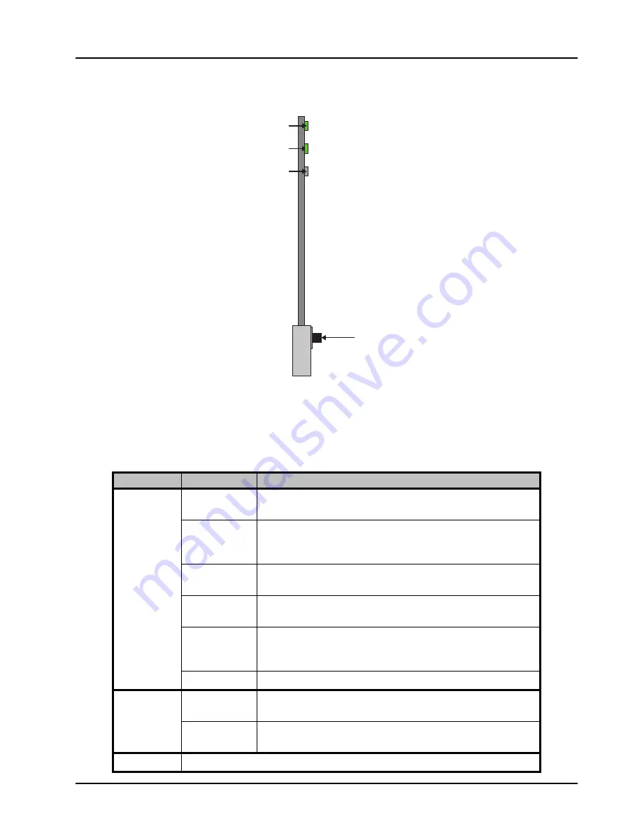
The following sections describe the card-edge LEDs. Refer to 

Figure 3.2

 for LED locations.

Figure 3.2  

LED Locations

Status LEDs

Basic LED displays and descriptions are provided in 

Table 3.1

Table 3.1  Status LEDs

LED

Color

Display and Description

PWR

Green

When lit green, this LED indicates that the card is functioning 
normal and that no anomalies have been detected.

Flashing Green

When flashing green, this LED indicates that the Bootload button 
was pressed, and the card is receiving a new software load from 
the frame.

Flashing Green 
and Orange

When lit green with flashing orange, this LED indicates a signal 
or configuration problem. Verify the signal status and settings.

Amber

When lit amber, this LED indicates the card is running internal 
diagnostics while powering up.

Red

When lit red or flashing red, this LED indicates the card is not 
operational. Re-seat card in frame, check the rear module type 
and connections, or call Ross Video Technical Support.

Off

When off, this LED indicates there is no power to the card.

INPUT A

Green

When lit green, this LED indicates that a valid SDI input signal is 
present on Channel A.

Red

When lit red, this LED indicates that the SDI input signal is 
missing or invalid on Channel A.

AUX IN

This LED is not implemented.

Bootload Button

PWR LED

INPUT A LED

AUX IN LED

Summary of Contents for openGear SEA-8803

Page 1: ...SEA 8803 Single 3G HD SD Equalizing Distribution Amplifier User Manual...

Page 2: ...eople that make things happen At Ross our employees are a special group Our employees truly care about doing a great job and delivering a high quality customer experience every day This code of ethics...

Page 3: ...tted in any form or by any means mechanical photocopying recording or otherwise without the prior written permission of Ross Video While every precaution has been taken in the preparation of this docu...

Page 4: ...t avoided may result in major or minor equipment damage or a situation which could place the equipment in a non compliant operating state ESD Susceptibility This symbol is used to alert the user that...

Page 5: ...ith the essential requirements and other relevant provisions of CE Directive 93 68 EEC INTERNATIONAL This equipment has been tested to CISPR 22 1997 along with amendments A1 2000 and A2 2002 and found...

Page 6: ...ral resources Ross Video encourages you to use the appropriate take back systems These systems will reuse or recycle most of the materials from your end of life equipment in an environmentally friendl...

Page 7: ...1K0 Ogdensburg New York Canada USA 13669 0880 General Business Office 1 613 652 4886 Fax 1 613 652 4425 Technical Support 1 613 652 4886 After Hours Emergency 1 613 349 0006 E mail Technical Support t...

Page 8: ......

Page 9: ...Conventions 1 6 Installation 2 Before You Begin 2 2 Static Discharge 2 2 Unpacking 2 2 Installing the SEA 8803 2 3 Supported Rear Modules 2 3 Installing a Card 2 3 Cabling 2 5 Software Upgrades 2 7 Co...

Page 10: ...ii Contents SEA 8803 User Manual Iss 02 Service Information 6 Troubleshooting Checklist 6 2 Bootload Button 6 2 Warranty and Repair Policy 6 3...

Page 11: ...pment family of products backed by Ross Video s experience in engineering and design expertise since 1974 You will be pleased at how easily your new card fits into your overall working environment Equ...

Page 12: ...PTE 310 signals Flexible channel configurations Operate as single 1x8 requires the 8320AR 300 Full Rear Module Operate as single 1x8 with a bypass relay between SDI IN and OUT 1 requires the 8320AR 30...

Page 13: ...module This configuration has the SEA 8803 operating as a single equalizing 1x8 with BNC connections Figure 1 1 Simplified Diagram 1x8 Configuration 8320AR 300 Single 1x8 Configuration with Bypass Rel...

Page 14: ...1 3 describes the workflow of the SEA 8803 with the 8320AR 301 Split Rear module This configuration has the SEA 8803 operating as a single equalizing 1x4 with BNC connections Figure 1 3 Simplified Di...

Page 15: ...hBoard User Manual Card edge Monitoring The card edges provide LEDs for monitoring the status of the input signal For More Information on card edge LEDs refer to the section Monitoring Features on pag...

Page 16: ...fers to the MFC 8320 N MFC 8322 S and MFC OG3 N Series Network Controller Cards unless otherwise indicated OG3 FR series refers to the OG3 FR series frames and all available options unless otherwise i...

Page 17: ...chapter provides instructions for installing the rear module for your SEA 8803 installing the card in the frame cabling details and how to upgrade the software on your card s The following topics are...

Page 18: ...Unpack each card you received from the shipping container and ensure that all items are included If any items are missing or damaged contact your sales representative or Ross Video directly ESD Susce...

Page 19: ...slot within an openGear frame This section outlines how to perform both tasks To install the rear module in the openGear frame 1 Ensure that the openGear frame is properly installed 2 On the rear of...

Page 20: ...ar Module Label to the BNC area of the Rear Module 9 Ensure proper frame cooling and ventilation by having all rear frame slots covered with rear modules or blank metal plates To install the card in t...

Page 21: ...Connections for the 8320AR 300 Full Rear Module Single 1x8 Configuration with Bypass Relay The 8320AR 306 Full Rear Module is required when operating as a single 1x8 configuration with a bypass relay...

Page 22: ...x4 configuration Each rear module occupies two slots and accommodates two cards This rear module provides one SDI input and four SDI outputs via BNC connections per card Figure 2 4 Figure 2 4 Cable Co...

Page 23: ...dialog Proceed to step 8 7 If you are upgrading multiple cards Click Next to display the Select Destination menu This menu provides a list of the compatible cards based on the card selected in step 2...

Page 24: ...2 8 Installation SEA 8803 User Manual Iss 02...

Page 25: ...tion 3 1 Configuration In This Chapter This chapter provides a general overview of the user controls available on your SEA 8803 The following topics are discussed Card Overview Monitoring Features Usi...

Page 26: ...and setup is done using the menus in DashBoard Refer to Figure 3 1 for location of this button Figure 3 1 Card edge Controls 1 Bootload Button This button is used for factory service in the unlikely...

Page 27: ...me Flashing Green and Orange When lit green with flashing orange this LED indicates a signal or configuration problem Verify the signal status and settings Amber When lit amber this LED indicates the...

Page 28: ...with your SEA 8803 card s is displayed in the Tree View located on the left side of the DashBoard window It may take 30 seconds or more to update the Tree View Consult the MFC 8300 Series or MFC OG3 S...

Page 29: ...chapter Specifications on page 5 1 for information on the cable equalization specifications for your card To enable the equalizer 1 From the Device View select the Setup tab Setup Tab Enabling the Equ...

Page 30: ...Signal tab This occurs if the SEA 8803 does not detect a valid input signal for that channel To verify which BNC to troubleshoot refer to the rear module labeling or the Input BNC field in the Setup...

Page 31: ...he menus items and parameters available from DashBoard for your card Default parameters are noted with an asterisk The following topics are discussed Status Tabs Setup Tab Alarms Tab Operating Tip Wai...

Page 32: ...ut signal is not present The Alarm on Loss of Input for this channel is disabled Input No signal Input signal is not present 125mB s signal A signal detected at less than 125Mbps is present SD signal...

Page 33: ...card does not align with the connector on the rear module Voltage mV Supply voltage Current mA Current consumption of card in milliAmperes CPU Headroom Processing power available RAM Available On boa...

Page 34: ...d as inputs for the channel Output BNCs read only Indicates the BNCs on the rear module that are assigned as the outputs N C Indicates that there are no outputs in this channel Enable Equalizer Select...

Page 35: ...able 4 5 Alarm Enables Menu Items Menu Title Item Parameters Description Channel A Alarm on Loss of Input Selected The Status field in the Signal tab reports the loss of the input as an error alarm Cl...

Page 36: ...4 6 DashBoard Menus SEA 8803 User Manual Iss 02...

Page 37: ...ications 5 1 Specifications In This Chapter This chapter includes the technical specifications for the SEA 8803 Note that specifications are subject to change without notice The following topics are d...

Page 38: ...01 500m 1640ft of Belden 1694A cable 270Mbps 200m 650ft of Belden 1694A cable 1 485Gbps 120m 394ft of Belden 1694A cable 2 97Gbps 8320AR 306 500m 1640ft of Belden 1694A cable 270Mbps 200m 650ft of Bel...

Page 39: ...SEA 8803 User Manual Iss 02 Service Information 6 1 Service Information In This Chapter This chapter contains the following sections Troubleshooting Checklist Warranty and Repair Policy...

Page 40: ...that the power supplies are fully seated in their slots If the power LED is still not illuminated replace the power supply with one that is verified to work 3 Input Signal Status Verify that source eq...

Page 41: ...his User Manual provides all pertinent information for the safe installation and operation of your openGear Product Ross Video policy dictates that all repairs to the SEA 8803 are to be conducted only...

Page 42: ...Notes...

Page 43: ...Notes...

Page 44: ...trade show information Visit Us Visit our website for Company information and news Related products and full product lines Online catalog Testimonials Technical Support Telephone 1 613 652 4886 After...

Reviews: