Rose electronics CNV-VGADVISC Installation And Operation Manual Download Page 8

MODELS 

Rose Translator Installation and Operation Manual 


Rose Translator Models 

The Rose Translator comes in a single model as shown below. 
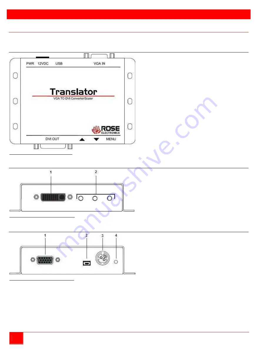
Top View 


Figure 1. Rose Translator Top View 

Front View 


Figure 2. Rose Translator Front View


Buttons / Connectors: 

1. 

DVI OUT:

 Use a DVI cable to connect a DVI 

display to this port. 

2. 

MENU:

 These push buttons are used to 

change settings within the on-screen menu 
system. See the Rose Translator Menu 
System section on page 4 for more 
information. 

Rear View 


Figure 3. Rose Translator Rear View 

Connectors / Indicators: 

1.  VGA IN:

 Connect included VGA cable from 

source device (e.g. computer) to this port


2.  USB:

 This mini-USB port is reserved for use 

by Rose Electronics.


3.  12V DC:

 Connect included 12V DC power 

supply to this power receptacle.


4.  PWR:

 Under normal operating conditions, this 

LED indicator will glow bright blue.


Summary of Contents for CNV-VGADVISC

Page 1: ...Translator VGA To DVI Converter Scaler 10707 Stancliff Road Houston Texas 77099 Phone 281 933 7673 www rose com INSTALLATION AND OPERATIONS MANUAL...

Page 2: ......

Page 3: ...CHANTABILITY AND FITNESS FOR A PARTICULAR PURPOSE ARE LIMITED IN DURATION TO A PERIOD OF ONE YEAR FROM THE DATE OF PURCHASE AND NO WARRANTIES WHETHER EXPRESS OR IMPLIED WILL APPLY AFTER THIS PERIOD SO...

Page 4: ...ure Menu Item 9 Contrast 9 Brightness 10 Saturation 11 Hue 12 Color Range 13 Color Temperature 14 Color Balance 15 Edge Enhance 16 Sharpness 17 Adjustment Menu Item 18 Under scan Over scan 18 Aspect R...

Page 5: ...lection Box 13 Figure 30 Picture Submenu with Color Temp Highlighted 14 Figure 31 Color Temp Selection Box 14 Figure 32 Picture Submenu with Color Balance Highlighted 15 Figure 33 Color Balance Select...

Page 6: ...he Video Converter and Scaler 31 Figure 68 Output Setup Submenu System 35 Figure 69 Picture Submenu System 36 Figure 70 Adjustment Submenu System 37 Figure 71 System Submenu System 38 Figure 72 Test P...

Page 7: ...rs can be connected to a DVI video display using the VGA to DVI Converter Scaler The video can be scaled up to 1080p Full HD and 1920 x 1200 WUXGA An intuitive and comprehensive on screen display OSD...

Page 8: ...These push buttons are used to change settings within the on screen menu system See the Rose Translator Menu System section on page 4 for more information Rear View Figure 3 Rose Translator Rear View...

Page 9: ...luded VGA cable from the video source e g a computer to the VGA IN port on the unit 2 Connect a DVI cable from the DVI OUT port to a DVI display 3 Connect the included power supply to the 12V DC power...

Page 10: ...nd control all video features To display the menu system press the MENU button on the front panel Figure 5 Menu Controls on the Rose Translator The menu system will be displayed in the upper left corn...

Page 11: ...cted Figure 7 Main Menu and Submenus Use the or button on the front panel to highlight the desired item within the main menu For example if the button is pressed three times the System menu item is hi...

Page 12: ...nd the following will be displayed Figure 11 Selected Submenu Item Press the MENU button to return to the menu system Figure 12 Menu System is Redisplayed after Submenu Item Selection To exit the subm...

Page 13: ...e MENU button to select the Output Resolu submenu item 4 The Output Resolu selection box will be displayed Figure 16 Output Resolution Selection Box 5 Use the or button to select the desired resolutio...

Page 14: ...he MENU button to return to the Output Setup menu Figure 19 Return to Output Setup Menu 11 Use the or button to select the Back submenu item 12 Press the MENU button 13 Use the or button to select the...

Page 15: ...n to display the Picture submenu The Contrast submenu item will be highlighted Figure 20 Picture Submenu with Contrast Highlighted 4 Press the MENU button to select the Contrast submenu item 5 The Con...

Page 16: ...ighlight the Brightness submenu item Figure 22 Picture Submenu with Brightness Highlighted 5 Press the MENU button to select the Brightness submenu item 6 The Brightness selection box will be displaye...

Page 17: ...ighlight the Saturation submenu item Figure 24 Picture Submenu with Brightness Highlighted 5 Press the MENU button to select the Saturation submenu item 6 The Saturation selection box will be displaye...

Page 18: ...e the or button to highlight the Hue submenu item Figure 26 Picture Submenu with Hue Highlighted 5 Press the MENU button to select the Hue submenu item 6 The Hue selection box will be displayed Figure...

Page 19: ...hlight the Color Range submenu item Figure 28 Picture Submenu with Color Range Highlighted 5 Press the MENU button to select the Color Range submenu item 6 The Color Range selection box will be displa...

Page 20: ...highlight the Color Temp submenu item Figure 30 Picture Submenu with Color Temp Highlighted 5 Press the MENU button to select the Color Temp submenu item 6 The Color Temp selection box will be display...

Page 21: ...NU button to select the Color Balance submenu item 6 The Color Balance selection box will be displayed Figure 33 Color Balance Select Color Selection Box 7 Use the or button to select between Red Ch B...

Page 22: ...ht the Edge Enhance submenu item Figure 35 Picture Submenu with Edge Enhance Highlighted 5 Press the MENU button to select the Edge Enhance submenu item 6 The Edge Enhance selection box will be displa...

Page 23: ...ess submenu item Figure 37 Picture Submenu with Sharpness Highlighted 5 Press the MENU button to select the Sharpness submenu item 6 The Sharpness selection box will be displayed Figure 38 Sharpness S...

Page 24: ...be highlighted Figure 39 Adjustment Submenu with Under Over Scan Highlighted 4 Press the MENU button to select the Under Over Scan submenu item 5 The Under Over Scan selection box will be displayed F...

Page 25: ...ht the Aspect Ratio submenu item Figure 41 Adjustment Submenu with Aspect Ratio Highlighted 5 Press the MENU button to select the Aspect Ratio submenu item 6 The Aspect Ratio selection box will be dis...

Page 26: ...ubmenu with H Mirror Highlighted 5 Press the MENU button to select the H Mirror submenu item 6 The H Mirror selection box will be displayed Figure 44 Horizontal Mirror Selection Box 7 Use the or butto...

Page 27: ...t Submenu with V Mirror Highlighted 5 Press the MENU button to select the V Mirror submenu item 6 The V Mirror selection box will be displayed Figure 47 Vertical Mirror Selection Box 7 Use the or butt...

Page 28: ...Figure 49 Adjustment Submenu with H Shift Highlighted 5 Press the MENU button to select the H Shift submenu item 6 The H Shift selection box will be displayed Figure 50 Horizontal Shift Selection Box...

Page 29: ...item Figure 51 Adjustment Submenu with V Shift Highlighted 5 Press the MENU button to select the V Shift submenu item 6 The V Shift selection box will be displayed Figure 52 Vertical Shift Selection B...

Page 30: ...se the or button to highlight the Phase submenu item Figure 53 Adjustment Submenu with Phase Highlighted 5 Press the MENU button to select the Phase submenu item 6 The Phase selection box will be disp...

Page 31: ...em will be highlighted Figure 55 System Submenu with OSD Timeout Highlighted 4 Press the MENU button to select the OSD Timeout submenu item 5 The OSD Timeout selection box will be displayed Figure 56...

Page 32: ...selection box will be displayed Figure 58 Display Notify Selection Box 7 Use the or button to toggle between On and Off When Display Notify is set to On the input output resolution information dialog...

Page 33: ...or button to highlight the Input Res Info submenu item Figure 59 System Submenu with Input Res Info Highlighted 5 Press the MENU button to select the Input Res Info submenu item 6 The current input r...

Page 34: ...tton to highlight the F W Version submenu item Figure 61 System Submenu with F W Version Highlighted 5 Press the MENU button to select the F W Version submenu item 6 The current version of firmware on...

Page 35: ...e 63 System Submenu with Factory Reset Highlighted 5 Press the MENU button to select the Factory Reset submenu item 6 The Factory Reset selection box will be displayed Figure 64 Factory Reset Selectio...

Page 36: ...on to highlight the Test Patterns menu item 3 Press the MENU button to display the Test Patterns submenu The White submenu item will be highlighted Figure 65 Test Patterns Submenu with White Highlight...

Page 37: ...ank Figure 67 Dip Switch on the Video Converter and Scaler By default the dip switch is in the OFF 1 position The dip switch should remain in this position during normal operation Dip Switch Descripti...

Page 38: ...only power cords power adapter and connection cables designed for this Unit Keep objects that might damage this Unit and liquids that may spill clear from this Unit Liquids and foreign objects might...

Page 39: ...r or equivalent insured and shipped to Rose Electronics Attn RA__________ 10707 Stancliff Road Houston Texas 77099 USA Technical Support If you are experiencing problems or need assistance in setting...

Page 40: ...rface DVI Maximum Input Resolution 1920 x 1200 60Hz Maximum Output Resolution 1920 x 1200 60Hz 2048 x 1080 60Hz Maximum Pixel Clock 165 MHz Maximum TDMS Clock 165 MHz Connectors Video input VGA HD15 f...

Page 41: ...f each menu item in the menu system Note In each of the figures below the boxes in green indicate the default setting Output Setup Menu Figure 68 Output Setup Submenu System Denotes output resolution...

Page 42: ...36 Rose Translator Installation and Operation Manual Picture Menu Figure 69 Picture Submenu System...

Page 43: ...Rose Translator Installation and Operation Manual 37 Adjustment Menu Figure 70 Adjustment Submenu System...

Page 44: ...38 Rose Translator Installation and Operation Manual System Menu Figure 71 System Submenu System...

Page 45: ...Rose Translator Installation and Operation Manual 39 Test Patterns Menu Figure 72 Test Patterns Submenu System Exit Menu System Figure 73 Exit Submenu System...

Page 46: ...el 50 Color Balance Red Channel 50 Color Range Limited Color Temperature Neutral Contrast 50 Display Notifications On Edge Enhancement Off Horizontal Mirror Off Horizontal Shift Off Hue 50 OSD Timeout...

Page 47: ...screws not included There should be an inch or two of clearance between the edges of the unit and any walls or vertical surfaces to allow for sufficient clearance for the connection and disconnection...

Page 48: ...10707 Stancliff Road Houston Texas 77099 Phone 281 933 7673 www rose com...

Reviews: