Check the mechanics of the missing functionality to ensure that all parts can move freely
and belts are properly in place.
If all else fails, the module can be slid partially out of the unit so that the connections can
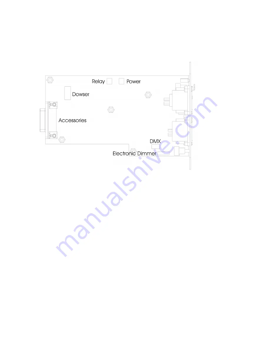
be checked. The diagram below shows the location of key connections.
For the most part, connectors can be matched up to headers on the PCB. The only
exception is the relay and power headers, which are identical. The relay cable uses two
blue wires while the power cable uses a red/black combination.


