ROPV R80 1000S User Manual Download Page 10

ROPV R80 S Series Manual  

August 

2005B 

Head Installation 

 
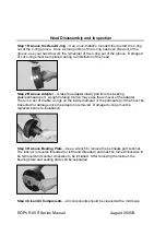
Step 1 Follow All Steps Outlined in the Head Reassembly Section
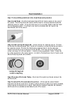


Step 2 Install Head 

– Hold the head assembly with both hands, square to the axis of 

the vessel.  Push firmly with both hands until the head is correctly positioned and the 
retaining groove is visible.  It may be necessary to use a rubber mallet to tap the head 
into its engaged position.  The thrust cone must be installed with the head at the 
downstream end of the vessel. 


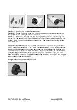
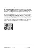
Step 3 Install Locking Kit Segments 

– Clean and dry the retaining groove.  Position 

the first two locking segments (No.1 and No.2 in picture)  so that the end section sits in 
the retaining groove.  Position the third locking segment (No.3) into the last area.  
Position the securing ring as shown and use an M6 / 7/32” hex wrench to tighten the 
screw until snug.  Do not over-tighten – maximum torque guideline: 10Nm.  Install the 
two other segments in the same manner.  Conduct a final tightness check of each screw 
after all three segments are installed. 


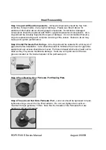
Step 4 Reconnect Permeate Piping 

– Reconnect the system permeate piping to the 

permeate port. 

 
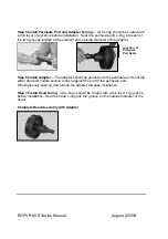
Step 5 Conduct Pre-Pressurization Inspection 

– A thorough pre-pressurization 

inspection should be conducted, including verifying that the heads are properly installed, 
system piping connections are in place, elements are installed, adapters are installed, 
and thrust cone is installed at downstream end of the vessel.


Locking Kit Segment 

and Securing Ring 

Summary of Contents for R80 1000S

Page 1: ...er Manual For Use with the Following ROPV Pressure Vessel Models R80 600S R80 800S R80 1000S R80 1200S Headquarters Harbin ROPV Industry Development Center 100 Hongqi St Xiangfang District Harbin Chin...

Page 2: ...ery precaution contained therein Failure to do so may result in malfunction and potential catastrophic failure It is recommended that only qualified technicians experienced in servicing hydraulic syst...

Page 3: ...d closures regularly for signs of corrosion Immediate corrective action and or replacement is suggested in case of corrosion Relieve system pressure before working on the vessel Do not attempt to over...

Page 4: ...h 3 locking screws The locking screws can be removed using an M6 7 32 hex wrench The locking screws should be unthreaded from the head only not from the locking segment The locking screw and locking s...

Page 5: ...e the head once it has cleared the retaining groove area of the vessel Alternative Head Removal It is possible to remove the head assembly without the ROPV head removal tools A 1 NPT Male threaded pie...

Page 6: ...aring plate permeate port A slight rotating motion may ease the removal of the adapter There is a set of double o rings on the inside diameter of the permeate port that must be inspected for damage on...

Page 7: ...r system performance Step 6 Inspect Inside Vessel Surface The inside surface of the vessel should also be inspected once the membrane elements have been removed Special attention should be paid to ide...

Page 8: ...or system performance Step 2 Install Permeate Port O rings All o rings should be coated with a thin layer of glycerine before installation Care should be used to minimize the amount or glycerine appli...

Page 9: ...er Step 6 Install Adapter The adapter should be pushed into the permeate port until the wider diameter middle section is flush against the end of the permeate port Simultaneously pushing and turning t...

Page 10: ...the end section sits in the retaining groove Position the third locking segment No 3 into the last area Position the securing ring as shown and use an M6 7 32 hex wrench to tighten the screw until sn...

Page 11: ...ROPV R80 S Series Manual August 2005B Step 6 Pressurize System Step 7 Inspect for Leaks All connections should be free from leaks Do not operate leaking vessels...

Page 12: ...m the port to the manifold is less than 0 03 per port Make sure the vessel is centered on the rack when checking for port manifold alignment Using intermediate flexible Victaulic connections in the ma...

Page 13: ...Port Locknut 8014 1 Feed Conc Port Retaining Ring 80051 Feed Conc Port 8018 1 8018 2 8018 3 8018 4 Thrust Ring 8022 3 Adapter 8026 Strap 8027 3 Strap Screw 8029 Securing Ring 8035 Securing Ring Screw...

Page 14: ...ions for warranty performance and ROPV reserves the right to conduct warranty performance outside of the items shown If the Product is found by ROPV to be defective under the terms of this warranty RO...

Page 15: ...ROPV R80 S Series Manual August 2005B...

Page 16: ...ROPV R80 S Series Manual August 2005B...

Page 17: ...ROPV R80 S Series Manual August 2005B...

Page 18: ...ROPV R80 S Series Manual August 2005B...

Reviews: