Ropex RESISTRON RES-409 Operating Instructions Manual Download Page 31

Controller functions

Version 1

RES-409

Page 31

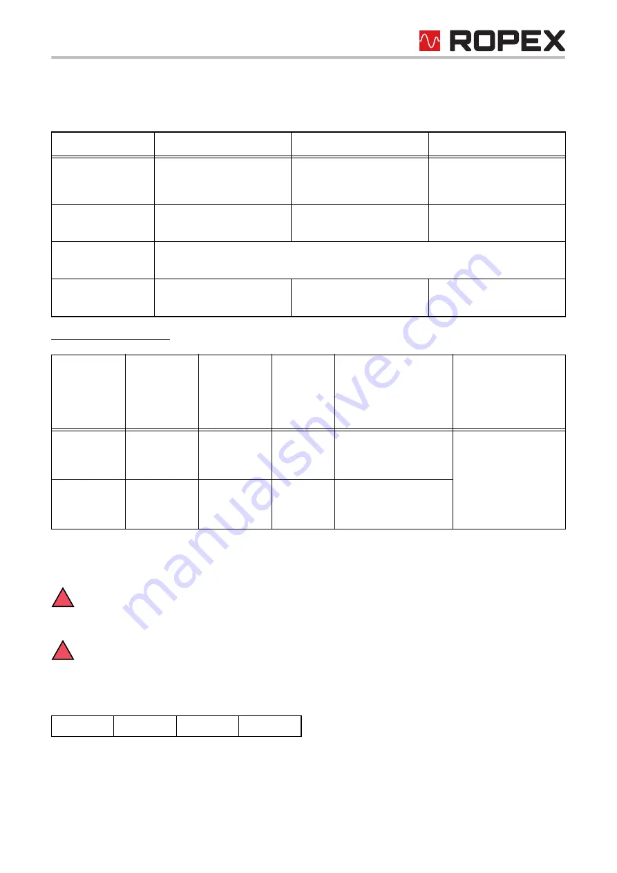
In addition to the functions shown in the diagram above, various controller operating states are indicated by the
LEDs. These states are described in detail in the table below:

As of February 2007 also:

10.2

CAN protocol

The following sections describe only controller-specific functions. For general information about
the CAN bus and the system configuration, please refer to the description provided by your PLC

manufacturer.

The CAN BUS-interface of the RES-409 supports CAN 2.0A according ISO 11898. CANopen is not
supported.

The CAN messages of the RES-409 always consist of 4 bytes. The first two bytes form a 16-bit address and the
last two a 16-bit value:

"Address.H" is the first byte to be transferred while "value L" is transferred last.

LED

Blinks slowly (1Hz)

Blinks fast (4Hz)

Lit continuously

AUTOCAL

(yellow)

Indicates undervoltage

AUTOCAL requested but 

function is locked

(as of February 2007)

AUTOCAL is running

HEAT

(yellow)

START requested

but function is locked

START is running

OUTPUT

(green)

In control mode, luminous intensity is proportional to heating current

FAULT

(red)

Configuration error, cannot 

run AUTOCAL

Controller calibrated 

incorrectly, run AUTOCAL

Error (

section 10.16)

LED

Blinks

once

(red)

Blinks

twice

(red)

Lit (red)

Lit (green)

NETWORK STATUS

blinks (red)

MODULE STATUS

blinks (green)

(alternately)

NETWORK

STATUS

(green/red)

CAN

controller:

Warning

CAN

controller:

Passive level

CAN

controller:

Bus off

Data transfer via CAN 

interface

AutoBaud active

(

section 9.2.5)

MODULE

STATUS

(green/red)

Microcontroller

status OK

Address.H

Address.L

Value.H

Value.L

Byte 1

Byte 2

Byte 3

Byte 4

!

!

Summary of Contents for RESISTRON RES-409

Page 1: ...ic zero calibration AUTOCAL Automatic optimization AUTOTUNE Automatic configuration of the secondary voltage and current ranges AUTORANGE as of February 2007 Automatic phase angle compensation AUTOCOMP as of February 2007 Automatic frequency adjustment Large current and voltage range 0 10VDC analog output for ACTUAL temperature Additional 24VDC control signals for START 0 Set 0 and START 1 Set 1 a...

Page 2: ... View of the controller 22 9 2 Controller configuration 22 9 3 Heatsealing band 27 9 4 Startup procedure 28 10 Controller functions 30 10 1 Indicators and controls 30 10 2 CAN protocol 31 10 3 Receiving CAN messages 32 10 4 Sending CAN messages 38 10 5 Temperature meter actual value output 42 10 6 Hold mode 43 10 7 Measuring impulse length as of February 2007 45 10 8 Automatic phase compensation A...

Page 3: ...g bands which are expressly approved for them and providing the regulations notes and warnings contained in these instructions are observed In case of non observance or use contrary to the intended purpose there is a risk that safety will be impaired or that the heatsealing band electrical wiring transformer etc will overheat This is the personal responsibility of the user 1 3 Heatsealing band The...

Page 4: ... instructions contained in section Power supply must be observed External monitoring modules can be used in order to additionally increase operating safety They are not included in the scope of supply of the standard control system and are described in a separate document 1 6 Line filter ROPEX provides line filters in different power classes The ROPEX application report lists the suitable line fil...

Page 5: ...ally sound way To guarantee proper disposal and or the recover of reusable material please take the device to a designated municipal collection point and observe local regulations Careless uncontrolled disposal can cause damage to the environment and human health By ensuring that your product is disposed of or recycled in a responsible way you can help protect the environment and human health This...

Page 6: ...ry significantly in terms of performance and physical dimensions All information provided by us in connection with the line filter is merely intended as a guide and is based on a typical measuring setup It serves to demonstrate that compliance with the EMC directive can be achieved by using a line filter that is suitable for the overall system The line filter and current transformer must however b...

Page 7: ...e The temperature calculated with the help of these measurements is displayed and compared with the set point The primary voltage of the impulse transformer is adjusted by phase angle control if the measured values deviate from the set point The resulting change in the current through the heatsealing band leads to a change in the band temperature and thus also its resistance This change is measure...

Page 8: ... as overheating of the heatsealing band The RESISTRON temperature controller RES 409 is equipped with a CAN Bus interface type CAN 2 0A according ISO 11898 Remark CANopen is not supported This interface can be used to control all the controller functions and interrogate controller information The ACTUAL temperature of the heatsealing band is supplied to the CAN Bus interface and to an analog 0 to ...

Page 9: ... ATR x For front panel mounting or mounting on a top hat rail DIN TS35 rail Analog indication of the ACTUAL temperature of the heatsealing band in C The meter damping of the unit is optimized for the abrupt temperature changes that occur in impulse mode Digital temperature meter DTR x For front panel mounting or mounting on a top hat rail DIN TS35 rail Digital indication of the ACTUAL temperature ...

Page 10: ... Additional terminal for connecting an external switching amplifier booster This modification is necessary for high primary currents continuous current 5A pulsed current 25A This modification is supplied as standard with all controllers manufactured as of February 2007 section 10 13 Booster connection on page 50 Booster B xxx400 External switching amplifier necessary for high primary currents cont...

Page 11: ...20VAC 10 equivalent to 98 132VAC 230VAC version 230VAC 15 240VAC 10 equivalent to 196 264VAC 400VAC version 400VAC 15 415VAC 10 equivalent to 340 456VAC All controllers manufactured up to December 2003 115VAC 230VAC or 400VAC tolerance 10 15 depending on version selected section 13 How to order on page 60 Line frequency 47 63Hz automatic adjustment to frequencies in this range CAN Bus interface CA...

Page 12: ... 0 400 C 0 500 C Temperature coefficient 3500ppm e g LEX3500 0 200 C 0 300 C 0 400 C 0 500 C All controllers manufactured as of February 2007 The settings with the rotary coding switch are considered to be the factory setting This corresponds to CAN message address 8 value 10 dec section 10 3 Receiving CAN messages on page 32 All controllers manufactured up to January 2007 Six different ranges can...

Page 13: ...or mounting on a horizontal top hat rail End holders to mechanical fix the controller must be fitted at both ends for mounting on a vertical top hat rail Weight Approx 0 7kg incl connector plug in parts Housing material Plastic polycarbonate UL 94 V0 Connecting cables Type cross sections Rigid or flexible 0 2 2 5mm AWG 24 12 Plug in connectors If ferrules are used they must be crimped in accordanc...

Page 14: ...that all circuits are deenergized 2 The supply voltage specified on the nameplate of the RESISTRON temperature controller must be identical to the line voltage that is present in the plant or machine The line frequency is automatically detected by the temperature controller in the range from 47Hz to 63Hz 3 Install the RESISTRON temperature controller on a standard top hat rail DIN TS35 rail accord...

Page 15: ...ort The information provided in section 8 2 Installation steps on page 16 must be additionally heeded 5 Connect the RESISTRON temperature controller to the CAN master using a cable according to IEC 947 5 2 Check the tightness of all system connections including the terminals for the impulse transformer winding wires 6 Make sure that the wiring conforms to all relevant national and international in...

Page 16: ...bands with suitable temperature coefficient 20mm clearance if several controllers installed on one top hat rail Note polarity No additional resistance in secondary circuit Dimension transformer correctly Secondary voltage Power Duty cycle Configure DIP switches correctly Sufficient wire cross section No push on connectors Twisted Current measuring wires IR R Connect U measuring wires directly to h...

Page 17: ...s load side RESISTRON temperature controller Relay Kb Load break all pole e g in combination with the alarm output of the temp controller ROPEX recommendation When using a series resistor RV 1 the relay Kb shall be installed Impulse Transformer Designed according to EN 61558 isolating transformer with reinforced insulation Connect core to ground Use transformers with a one section bobbin The power...

Page 18: ...n Report calculated for your particular heatsealing application For more technical information Line filter documentation It is permissible to supply several RESISTRON control loops with a single line filter providing the total current does not exceed the maximum current of the filter The wiring instructions contained in section 8 3 Power supply on page 17 must be observed Example drawing for LF 06...

Page 19: ...rsion 1 RES 409 Page 19 8 5 1 PEX W4 8 5 2 PEX W5 Mounting on DIN rail 35 x 7 5 mm or 35 x 15 mm DIN EN 50022 Snap on for DIN rail 35 x 7 5 mm or 35 x 15 mm DIN EN 50022 terminal block terminal wires 14 60 24 75 14 23 28 26 39 12 ...

Page 20: ...externally to prevent electrostatic charging Bus GND Bus GND CAN bus Plug 1 3 pole CAN bus Plug 2 3 pole CAN bus Plug assignment RES 409 START 0 Set 0 with 24 VDC signal START 1 Set 1 with 24 VDC signal ANALOG OUTPUT 0 10VDC RES 409 also with MOD 01 CAN bus Controller electrically isolated Impulse transformer Heatsealing band LINE Line filter LF xx480 sec Twisted 0V Internnal ground No external gr...

Page 21: ...lectrically isolated 4 4 1 1 3 3 L L Bus GND Bus GND H H CAN bus Plug 1 3 pole CAN bus Plug 2 3 pole CAN bus Plug assignment RES 409 6 5 7 START 0 Set 0 with 24 VDC signal START 1 Set 1 with 24 VDC signal GND R Current transformer Impulse transformer 11 9 10 8 IR UR Heatsealing band 18 17 C ATR _ ANALOG OUTPUT 0 10VDC 4 3 2 1 15 16 LINE Booster NC NC 2 4 IN OUT 1 3 Line filter LF xx480 sec U2 prim...

Page 22: ... voltage is configured in the range from 0 4VAC to 120VAC and the current in the range from 30A to 500A If the voltage and or current are outside the permissible range a detailed error message appears on the controller see section 10 16 Error messages on page 52 Configuration with DIP switches controllers manufactured up to January 2007 Set the DIP switches for matching the secondary voltage U2 an...

Page 23: ...AN message address 8 value 10 dec section 10 3 Receiving CAN messages on page 32 If the switch is set to 9 as of February 2007 other temperature ranges and alloys can be selected in the ROPEX visualization software see section 10 12 Diagnostic interface visualization software as of February 2007 3 2 1 4 5 ON OFF 1 10V 6 60V 20 120V ON OFF OFF OFF ON OFF OFF OFF ON 30 100A 60 200A 120 400A OFF ON O...

Page 24: ...on software see section 10 12 Diagnostic interface visualization software as of February 2007 on page 50 9 2 4 Configuration of the CAN interface The CAN interface of the RES 409 is configured with DIP switches The baud rate and some of the identifiers can be set It is also possible to activate a terminating resistance The CAN BUS interface of the RES 409 supports CAN 2 0A according ISO 11898 CANo...

Page 25: ...affic Until the correct baud rate is detected the controller only plays a passive role on the CAN bus and has no influence on communications The NETWORK STATUS LED red and the MODULE STATUS LED green blink alternately as long as the AutoBaud function is active If the baud rate for the CAN network is changed while the controller is operating it must be switched off and then on again in order to rea...

Page 26: ... value of 0 for receiving CAN messages The least significant bit has a fixed value of 1 for sending CAN messages The identifier for CAN messages sent by the RES 409 in other words always has a value one higher than for received CAN messages All controllers manufactured up to January 2007 Switches 5 1 of the 8 pole DIP switch determine the 5 high bits of the 11 bit long standard CAN identifier The ...

Page 27: ...ge burn in effect The cold resistance of the heatsealing band is reduced by approximately 2 3 However this at first glance slight resistance change results in a zero point error of 20 30 C The zero point must therefore be corrected after a few heating cycles section 9 3 2 Burning in the heatsealing band on page 27 One very important design feature is the copper or silver plating of the heatsealing...

Page 28: ...age und Installation on page 14 Proceed as follows to start up the controller for the first time 1 Switch off the line voltage and verify that all circuits are deenergized 2 The supply voltage specified on the nameplate of the controller must be identical to the line voltage that is present in the plant or machine The line frequency is automatically detected by the temperature controller in the ra...

Page 29: ... been calibrated successfully the red FAULT LED blinks slowly 1Hz In this case the controller configuration is incorrect section 9 2 Controller configuration on page 22 and ROPEX Application Report Repeat the calibration after reconfiguring the controller correctly 8 Burn in the heatsealing band section 9 3 Heatsealing band on page 27 and repeat the AUTOCAL function 9 4 2 Restart after replacing t...

Page 30: ... the CAN bus transmission as well as CAN bus error messages supply for the CAN bus interface is OK yellow LED ALARM red LED HEAT AUTOCAL green LED OUTPUT yellow LED Lights up or blinks to indicate an alarm Remains lit for duration of AUTOCAL process Lit during heating phase Indicates pulses in measurement mode In control mode luminous intensity is proportional to heating current 4 3 2 1 9 8 6 5 10...

Page 31: ...s H is the first byte to be transferred while value L is transferred last LED Blinks slowly 1Hz Blinks fast 4Hz Lit continuously AUTOCAL yellow Indicates undervoltage AUTOCAL requested but function is locked as of February 2007 AUTOCAL is running HEAT yellow START requested but function is locked START is running OUTPUT green In control mode luminous intensity is proportional to heating current FA...

Page 32: ...rature Query current upper temperature monitoring value see value 22 Query current value of heatsealing band alloy temperature range As of February 2007 Query current fault and AUTOCAL status Query current hold mode setting Query current AUTOCOMP status Query maximum set point Query current software revision Query current software version default value 00 Query current variable temperature coeffic...

Page 33: ... TCR 3500ppm K max temperature range 500 C Rotary coding switch setting applies TCR temperature range max set point is variable see addresses 000A 000B 0014 TCR 780ppm K max temperature range 200 C TCR 780ppm K max temperature range 300 C TCR 780ppm K max temperature range 400 C TCR 780ppm K max temperature range 500 C The following CAN messages are only available on controllers manufactured as of...

Page 34: ... the heatsealing band is not heated when the start stop command is activated 10 3 2 START STOP command START signal A START command or a START signal is rejected HEAT LED blinks fast if the AUTOCAL function is running or a RESET command is active The fault output is switched if a START command or the START signal is activated while a warning message with error codes 8 12 as of February 2007 also 1...

Page 35: ...ode Each START STOP command is answered with an acknowledgment message address 9 which also contains the 6 low bits of the controller status in addition to the actual temperature value By means of a 24VDC control signal controllers manufactured as of February 2007 A START STOP command for set points 0 and 1 can also be activated by means of a digital 24VDC control signal START 0 or START 1 When a ...

Page 36: ...calibration process takes around 10 15 seconds The heatsealing band is not heated The yellow LED on the front panel lights up when the AUTOCAL function is active The actual value output terminals 17 18 is set to 0 3 C corresponds to approx 0 VDC If the temperature of the heatsealing band varies on controllers manufactured as of February 2007 the AUTOCAL function is run a maximum of three times If ...

Page 37: ...ealing band alloy and temperature range are permanently stored in the controller and are not lost even if the power supply fails The current setting can be reloaded by means of CAN message address 11 The controller is delivered with the setting 1 in other words TCR 1100ppm and temperature range 300 C If Alloy range CAN message address 8 is set to Variable value 11 you can now specify the temperatu...

Page 38: ... in C Current set point 1 in C Current set point 2 in C Current set point 3 in C 0004 20 Tmax Current actual value in C 0005 10 4 1 Full current controller status 0006 3 digits BCD coded Digits 1 3 of 6 digit controller number 0007 3 digits BCD coded Digits 4 6 of 6 digit controller number 0008 0 40 Current calibration temperature in C 0009 10 4 2 Acknowledgment message current actual value with r...

Page 39: ...se length in 0 1ms 001A 0 3 Temperature range 0 200 C 1 300 C 2 400 C 3 500 C 001B 0 15 Current controller type RES 409 value 7 Bit no Name Meaning 0 1 Set point no Number of the last set point used 0 3 2 Controller active 0 Measuring mode 1 Control mode 3 Temperature OK 0 Actual value outside specified temperature tolerance band 1 Actual value inside specified temperature tolerance band 4 Fault 0...

Page 40: ...eached This status bit is set if the actual temperature exceeds 95 of the set temperature As soon as the control mode is exited or an alarm is signaled this status bit is reset again Bit no Name Meaning 0 8 Actual value Current actual value in C 9 Sign Sign of the actual value 0 positive 1 negative 10 11 Set point no Number of the last set point used 0 3 12 Controller active 0 Measuring mode 1 Con...

Page 41: ...ror code 10 11 Error action 0 Run RESET 1 Run AUTOCAL 2 Check configuration 12 15 AUTOCAL status 0 AUTOCAL function allowed not active and not locked 1 AUTOCAL function is active 2 Check for falling actual value 3 Wait until AUTOCAL request is canceled 4 Wait in case AUTOCOMP is started 5 AUTOCOMP function is active 6 AUTOCAL function is locked because heatsealing band is still hot 7 AUTOCAL funct...

Page 42: ...ls 17 18 Voltage values 0VDC 0 C 10VDC 300 C or 500 C depending on controller configuration The relationship between the change in the output voltage and the ACTUAL temperature is linear RES 409 17 max 5mA 18 0V R 33ohm Actual value output 0 10VDC 0 10VDC Temperature meter e g ATR 3 Bereich 0 300 C 1 2 3 4 5 6 7 8 9 10 300 Temperatur T C 20 C ZERO VDC Spannung U 60 90 120 150 180 210 240 270 0 66V...

Page 43: ... and accurately interpreted The same applies if mutual interference occurs between several neighboring control loops This output is not potential free and can carry the secondary voltage of the impulse transformer External grounding is not allowed If this warning is ignored the controller will be damaged by frame currents Shock protection must be provided If a fault occurs this analog output is us...

Page 44: ... then transferred again in real time until the end of the next heating phase Hold mode only applies to queries via the CAN interface The ACTUAL temperature always appears in real time at the analog actual value output The various hold modes are shown below ACTUAL temperature START command 24VDC T t t 0 0 Hold OFF T t 0 ACTUAL temp Hold ON T t 0 Hold 2 s T t 0 Hold Hold Hold Hold End of Heating pha...

Page 45: ...ay be necessary to compensate the phase angle displacement between the UR and IR measuring signals in certain heatsealing applications ROPEX Application Report The AUTOCOMP function is provided for this purpose CAN message address 13 The following settings are possible 1 OFF factory setting The AUTOCOMP function is deactivated 2 ON The AUTOCOMP function is executed whenever the AUTOCAL function se...

Page 46: ...actual value output terminals 17 18 is set to 0 3 C corresponds to approx 0VDC 3 AUTO as of software revision 102 This setting causes the AUTOCOMP function to be automatically started as soon as AUTOCAL has been successfully executed Mode AUTOCAL command 1 t t 0 0 AUTOCAL Lit t OFF 2 0s AUTOCOMP AUTOCAL t OFF LED Lit OUTPUT LED ...

Page 47: ...ture OK function is specified in CAN message address 9 The lower and upper tolerance band limits can be varied between 3 and 99 C up to January 2007 3 20 C with CAN message address 7 The upper and lower tolerance band limits can also be set independently of one another on controllers manufactured as of February 2007 CAN message addresses D and E The following settings are possible 1 Off Temperatur...

Page 48: ...ated in the ROPEX visualization software section 10 12 Diagnostic interface visualization software as of February 2007 on page 50 The RES 409 checks whether the ACTUAL temperature is within a settable tolerance band OK window either side of the SET temperature The lower and upper tolerance band limits are configured in the factory to 10K and 10K These values can be set independently of one another...

Page 49: ...es that can be set in the ROPEX visualization software for the upper and lower tolerance band are identical to those for the Temperature OK bit These values are transferred with CAN message address 7 or addresses D and E 10 11 Heatup timeout as of February 2007 An additional heatup timeout can be activated either in the ROPEX visualization software section 10 12 Diagnostic interface visualization ...

Page 50: ... set up to the ROPEX visualization software using the ROPEX CI USB 1 communication interface Only a ROPEX communication interface is allowed to be connected to the diagnostic interface Connecting another device e g a telephone cable could result in malfunctions or damage to the controller The ROPEX visualization software is described in a separate document 10 13 Booster connection All controllers ...

Page 51: ...software features that facilitate selective fault messages and diagnosis Both the external wiring and the internal system are monitored These features crucially support the system owner in localizing the cause of an abnormal operating state System faults are reported or differentiated by means of the following elements A Red FAULT LED on the controller lights up with three states 1 Blinks fast 4Hz...

Page 52: ...diagnosis can be carried out using the CAN protocol A two digit error code 4 bit can be queried for this purpose via CAN message address 4 value 4 section 10 4 1 Controller status on page 39 All controllers manufactured as of February 2007 support three digit error codes 10 bit as an additional option This can be queried with CAN message address 4 value 13 ƒ section 10 4 3 Fault AUTOCAL status as ...

Page 53: ... controller Check plug in jumper Cause I R signal missing U R signal missing U R and I R signals missing Temperature step down Temperature step up Temperature too low high section 10 10 Frequency fluctuation inadmissible line frequency Heatup time too long section 10 11 Int faut contr defective Triac defective Int faut contr defective Int faut contr defective Int faut contr defective Plug in jumpe...

Page 54: ...of transformer Fault area Run AUTOCAL and or fault area loose contact Run AUTOCAL Cause I R signals incorrect incorrect specification of impulse transformer U R signals incorrect incorrect specification of impulse transformer U R and or I R signals incorrect incorrect specification of impulse transformer Temperature too low AUTOCAL wasn t per formed loose contact ambient temp fluctuates temperatur...

Page 55: ...ation Fault area check configuration Fault area check configuration Cause I R signal incorrect calibration not possible U R signal incorrect calibration not possible U R and I R signals incorrect calibration not possible Temperature fluctuates calibration not possible Ext calibration temperature too high calibration not possible Ext calibration temperature fluctuates calibration not possible STATU...

Page 56: ...ture step Frequency fluctuation inadmissible line frequency Internal fault Internal fault controller defective U R and or I R signal incorrect Data error I R signal incorrect calibration not possible U R signal incorrect calibration not possible U R and I R signals incorrect calibration not possible STATUS of alarm relay factory set Energized De Energized gets energized with START signal voltage v...

Page 57: ...pickoff point Wire break Secondary winding of impulse transformer interrupted UR signal missing Measuring wires interrupted Partial short circuit delta R Heatsealing band partially bypassed by conducting part clamp opposite heatsealing bar etc Parallel circuit interrupted Wire break heatsealing band break Contacting to heatsealing band defective Total short circuit Heatsealing band installed incor...

Page 58: ... or incorrectly connected DIP switches for secondary voltage U2 and current I2 up to January 2007 U2 6 60VAC I2 30 100A DIP switches 2 ON 1 3 4 5 OFF These switches are automatically set by the AUTORANGE function on all control lers manufactured as of February 2007 Rotary coding switch for heatsealing band alloy and temperature range as of February 2007 Heatsealing band alloy Alloy A20 Temperature...

Page 59: ...r is recommended Dust deposits on the controller can be removed with dry compressed air Measuring impulse length X Measuring impulse length 1 7ms Temperature diagnosis X Temperature diagnosis OFF Heatup timeout X Heatup timeout OFF Output 1 X Temperature OK Bit aktive if Tact Tset Hold mode X Hold mode OFF DIP switch for identifier and baudrate As of February 2007 Identifier 0 Baudrate AutoBaud Te...

Page 60: ...the controller and the required modifications optional in all orders e g RES 409 400VAC MOD 01 controller for 400VAC power supply with amplifier for low voltage Art No 740903 800001 must be ordered Current transformer PEX W3 Art No 885105 Line filter LF 480 06 Continuous current 6A 480VAC Art No 885500 35 Continuous current 35A 480VAC Art No 885506 Impulse transformer See ROPEX Application Report ...

Page 61: ...How to order Version 1 RES 409 Page 61 Booster B 400 075 Max pulse load 75A 400VAC Art No 885301 100 Max pulse load 100A 400VAC Art No 885304 ...

Page 62: ... amplifier 10 21 F Factory settings 58 Fault areas 57 Fault diagnosis 8 Fault output 51 Fault relay 24 Fuse 17 H Heatsealing band alloy 37 Heatsealing band type 12 Heatup timeout 49 Hold mode 43 I Impulse heatsealing method 7 Impulse transformer 9 17 60 Installation 13 14 Installation procedure 14 Installation regulations 15 L Line filter 4 9 17 18 60 Line frequency 8 11 Line voltage 11 M Maintena...

Page 63: ...ature control 7 Temperature meter 9 42 43 60 Temperature monitoring 47 Temperature OK bit 47 Temperature range 12 23 37 Temperature reached bit 40 Transformer 4 9 17 60 Transportation 4 Type of construction 11 U Undervoltage detection 51 V Visualization software 50 W Wiring 15 17 ...

Reviews: