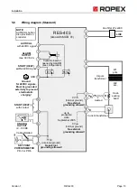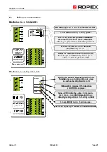
Controller functions
Page 22
RES-403
Version 1
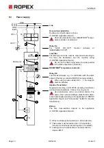
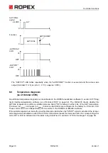
In addition to the functions shown in the diagram above, various controller operating states are indicated by the
LEDs. These states are described in detail in the table below:
6.2
Temperature setting (set point selection)
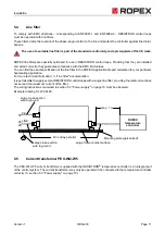
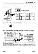
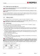
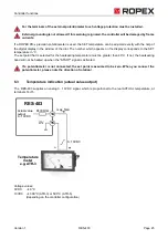
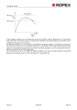
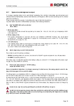
The heatsealing temperature is set by means of a 2k
Ω
potentiometer at terminals 16+17. The connecting wires
between the controller and the potentiometer must be shielded (
section 5.6 "Wiring diagram (Standard)" on
Setting range:
0
Ω
0°C
2k
Ω
300°C (PD-3) or 500°C (PD-5)
(depending on the controller configuration).
The relationship between the potentiometer setting and the SET temperature is linear.
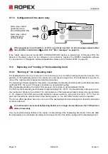
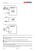
The terminals 16+17 are not potenial-free and might have the potential of the secondary voltage of
the impulse transformer.
LED
Blinks slowly (1Hz)
Blinks fast (4Hz)
Lit continuously
AUTOCAL
(yellow)
RESET active,
START and AUTOCAL
functions are locked
(as of October 2005)
AUTOCAL requested, but
function disabled
AUTOCAL executing
HEAT
(yellow)
—
START requested,
but function disabled
START executing
OUTPUT
(green)
In control mode the luminous intensity is proportional to the heating current.
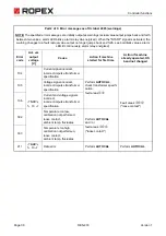
ALARM
(red)
Configuration error,
AUTOCAL not possible
Controller calibrated incor-
rectly, run AUTOCAL
Fault,
section 6.12
e.g.
PD-3
Potentiometer P03
with
digital dial KD
3
1
3
1
2
2
RES-403
0V
Set point
selection
input
17
16
cw
2K
Cable shielded
!

