ROOTS Rhino RD180 Operator'S Manual Download Page 48

48

Rhino RD180

MACHINE OPERATION

STARTING THE MACHINE

Before star ng the machine:

WARNING:


û

DO NOT SMOKE WHILE REFUELING OR TOPPING UP FLUIDS.

û

DO NOT REFUEL OR TOP UP NEAR OPEN FLAMES/FIRE.

û

DO NOT REFUEL OR TOP UP NEAR A HOT SURFACE.

û

DO NOT USE MOBILE PHONE REFUELING OR TOPPING UP FLUIDS.

WARNING:


DO NOT LET FUEL OR OIL TO LEAK INTO THE ENVIRONMENT. 
THERE IS A RISK OF CONTAMINATION!

If applicable use the above safety devices:

1. Safety Eyewear
2. Earmuff
3. Safety Reflec ng Jacket/Overalls
4. Safety Shoes
5. Safety Gloves
6. Dust Mask

1. Sit in operator seat, adjust seat posi on (if required) press parking brake, 

check if the direc on control pedal is in neutral posi on.

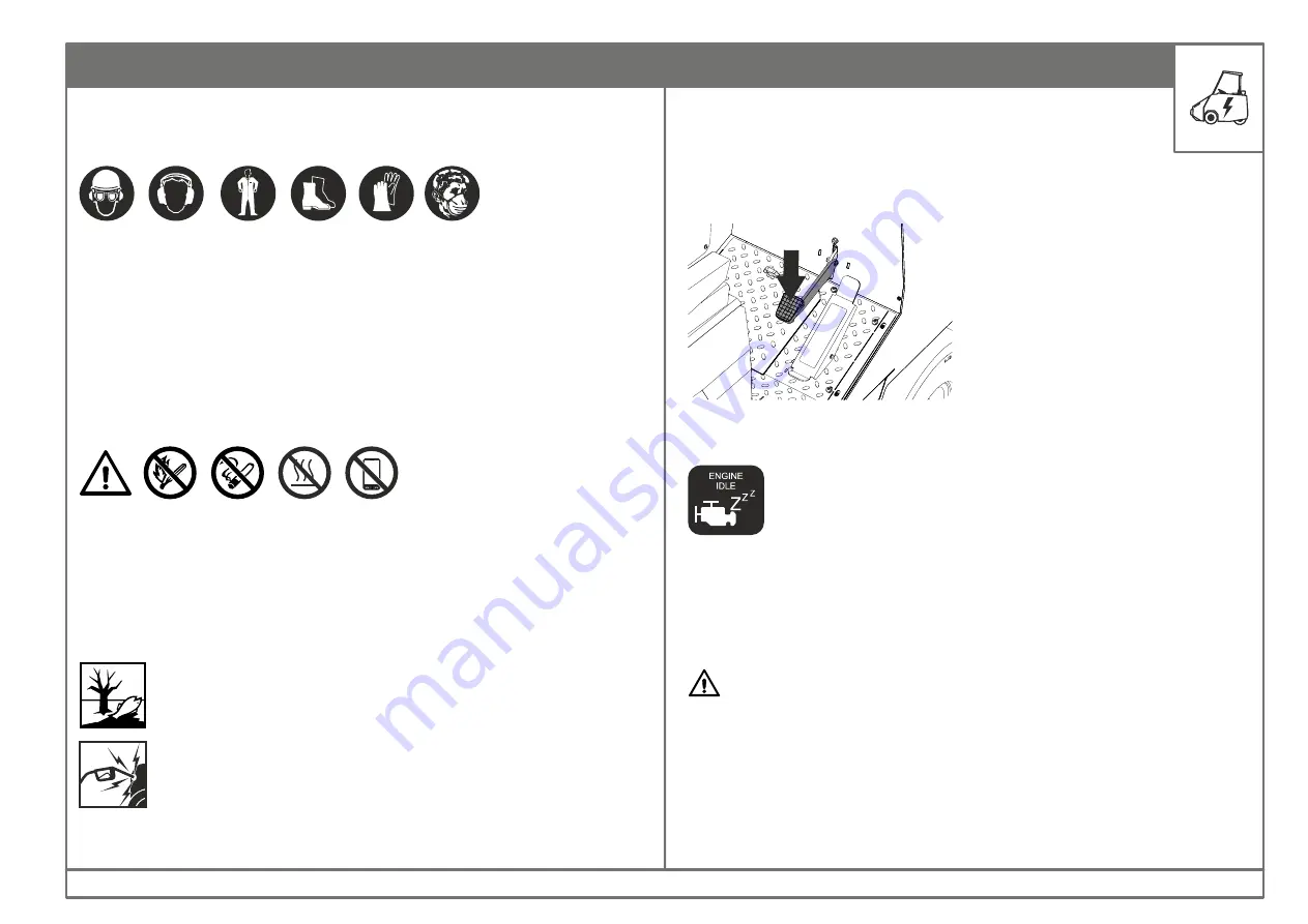
2. Thro le should be in 

idle

 posi on.

3. Turn the igni on key to start posi on to start the engine.

DRIVING THE MACHINE

NOTE: 

If the engine does not start after 10 seconds, release key, wait for 1 

minute and repeat the procedure again.

After starting the engine wait for two minutes with engine speed set to idle 
for the pneumatic system to pressurize. 

WARNING:  This  machine  emits  toxic  gases.  Severe  respiratory 
damage can be caused. Provide sufficient ventilation.

Idle engine speed

Star ng:

AVOID STATIC ELECTRICITY WHEN FUELING. AVOID DEATH OR 
SERIOUS INJURY FROM FIRE OR EXPLOSION. 

Summary of Contents for Rhino RD180

Page 1: ...1 Rhino RD180 Read this manual completely and understand the instructionsbeforeoperatingthemachine EnglishVersion RD180 Ride On Sweeper Diesel Operator s Manual...

Page 2: ...2 Rhino RD180...

Page 3: ...gine No _______________________________ Installation Date ___________________________ Introduc on Know Your Machine Ini al Set up Machine Opera on Troubleshoo ng Operator Notes Table Of Contents Impor...

Page 4: ...4 Rhino RD180 INTRODUCTION...

Page 5: ...cable general regulations pertaining to Safety and Health at the work place must be adheredtobytheuser Modifications made to machine without the manufacturer s consent will relieve the manufacturer of...

Page 6: ...to sweep hard floor surfaces in an indoor outdoor environment This machine is not intended for sweeping wet or slushy areas Do not use the machine on soil grass or artificial turf Use only recommende...

Page 7: ...7 Rhino RD180 TECHNICAL SPECIFICATION...

Page 8: ...Main Broom Length Main Broom Diameter Broom Type Bristle Type Side Broom Diamater 1420 mm 400 mm V Shape POLY WIRE 660 mm MAIN SIDE BROOM Unladen weight 2860 kg Without packing WEIGHT SWEEPING PERFOR...

Page 9: ...P ENGINE Hopper Volume Theore cal Dump Height Li Capacity 900 liters 1820 mm 900 kg HOPPER Filter Area 18 m No of Filters 9 FILTER Ba ery 12V 80Ah BATTERY Fuel DIESEL FUEL Diesel Tank 50 liters Hydrau...

Page 10: ...10 Rhino RD180 SAFETY INSTRUCTIONS...

Page 11: ...and is opera ng safelyprior to use Otherwise themachinemustnotbeused The machine is not suitable for sweeping dust which endangers health unless expressly speci ed otherwise Please follow the safety...

Page 12: ...star ng e g children Ensure su cientvisibility The machine may only be used by persons who have been instructed in handling the machine or have proven quali ca on and exper se in opera ng the machine...

Page 13: ...re poisonous and hazardous to health do not inhale them Read the opera ng instruc ons of the engine manufacturer before start upandfollowthesafetyinstruc onscarefully Riskofexplosion Pneuma c Tyres Eq...

Page 14: ...Throw In Garbage Informa on Environmental Hazard General Warning Ba ery Recycle Cau on No Fire Matches Toxic Hazard No Smoking No Passengers Do Not Throw In Garbage Hand Crush Hazard Hot Surface Sta c...

Page 15: ...15 Rhino RD180 SAFETY INSTRUCTIONS Wear Safety Glasses Wear Safety Helmet Wear Ear Mu Wear Respirator SYMBOLS HAZARDS PICTORIAL DEFINITIONS...

Page 16: ...ycling SAFETY INSTRUCTIONS Oldmachinescontainmaterialsthatcanberecycled Pleasearrangeforthe proper recycling of old machines Batteries electrical electronic components contain substances that must not...

Page 17: ...17 Rhino RD180 KNOW YOUR MACHINE...

Page 18: ...t Head Lamp w indicator 8 Rear Lamp w indicator 9 Work Lamp 10 Beacon Lamp 11 Side Broom 12 Operator Seat 13 Front Wheel with Brake 14 Hopper Dumping Door 15 Main Broom Access Door 16 Fuel Filler with...

Page 19: ...19 Rhino RD180 KNOW YOUR MACHINE 21 Panel Filter Purging System 22 Pneuma c Solenoid Valves 23 Panel Filter 24 Engine Group 15 21 22 23 24 10...

Page 20: ...20 Rhino RD180 Operator Orienta on 1 3 4 2 1 Front of the machine 2 Right of the machine 3 Rear of the machine 4 Le of the machine KNOW YOUR MACHINE...

Page 21: ...NOW YOUR MACHINE DECALS 1 2 3 1 Product category s cker 2 Manufacturer s logo s cker 3 Product name s cker 4 Hopper Thro le control s cker 5 Switch panel decal 6 Switch panel decal LH 7 Switch panel d...

Page 22: ...ker 2 Hopper li arm safety warning s cker 3 Rota ng belt keep away safety s cker 4 Diesel fuel safety s cker 5 Rota ng belt keep away safety s cker 6 Ba ery loca on warning s cker 7 Parking brake safe...

Page 23: ...YOUR MACHINE DECALS 1 3 5 6 2 4 1 Yellow Black stripe safety s cker 2 Yellow Black stripe safety s cker 3 Yellow Black stripe safety s cker 4 Grease point s cker 5 Safety stopper s cker 6 Commissionin...

Page 24: ...24 Rhino RD180 WORKING PRINCIPLE...

Page 25: ...eareatobesweptisdry Position the machine in the direction of the wind so that the wind blows thedustawayfromthemachine For optimum cleaning results match the driving speed with the area to beswept Swi...

Page 26: ...26 Rhino RD180 INITIAL SET UP...

Page 27: ...ethismachinetocollectanyhazardousdebris Donotusethismachineasatransportequipment WARNING Do not use this machine on surfaces exceeding a maximum of thegivenvalueforthegradientorslope ENVIRONMENTAL RES...

Page 28: ...iatetoolsandsafetydevices Upon Unloading l Check the machine for any transit damage such as dents paintdamage scratches leaks etc l Checkcoolantlevelintheradiator l Checktheengineoillevel l Checkthehy...

Page 29: ...29 Rhino RD180 CONTROLS...

Page 30: ...30 Rhino RD180 CONTROLS CONTROLLING AND INDICATING ELEMENTS 1 1 a 2 3 4 5 6 a b 7 a b 8 9 a b 10 11 12 13 14 15 16 17 18 19 20 21 22 23 27 24 25 26...

Page 31: ...ep Mode 9 b Intense Sweep Mode 10 Direc on Control Pedal 11 Brake Pedal 12 Parking Brake Lever 13 Indicator Switch 14 Horn Switch 15 Igni on Key Switch 16 Side Broom Adjustment Knob 17 Engine Oil Pres...

Page 32: ...nthesteeringwheeltotheright Thesteeringwheel ltlevercontrolstheangleofthesteeringwheel To adjust Rotate the lever towards the operator adjust the angle and push theleverbacktosecure 2 Thro le Lever Th...

Page 33: ...ises 3 Hopper Raise Lower Lever RAISE The hopper door open close are controlled via a lever on the operator console Leverposi onle ward Hopperdooropen Leverposi onrightward Hopperdoorclosed DOOR 4 Hop...

Page 34: ...onrightward DCSO Returntosweepmode 5 Debris Compact System DCS Lever 6 Impeller Filter Purging Switch COMPACT CONTROLS Impeller Filter Purge Switch This switch is used to switch On O the impeller and...

Page 35: ...sweep or intense sweep The switchhastwoposi onswhicharedescribedbelow The hour meter displays the total number of hours the machine has run This isusefultoschedulemaintenanceofthemachine Switch posi o...

Page 36: ...design to see the machine achieve lower speed during reversing than forward Neutral Take your foot o the direc onal pedal anditwillreturntotheneutralposi on Thebrakepedalisusedtosloworstopthemachine T...

Page 37: ...s come to a completestop Donotuseitonamovingmachineunlessitisanemergency CONTROLS The turn signal indicator switch is used to ac vate the indicator lamps located at the front and rear of the machine w...

Page 38: ...wered up START Engine starts Release the key as soon as the engine starts Thisknobisusedtoincreaseordecreasethesidebroompressure Rotatetheknobclockwisetodecreasepressure Rotatetheknoban clockwisetoinc...

Page 39: ...power and the needle will indicate 30 if any of the on board electrical equipment is drawing power 19 Ba ery Charging Gauge 30 0 30 The fuel level gauge indicates how much fuel is in the tank As the...

Page 40: ...at the machine is in opera on 24 Headlamp Switch 25 Warning Beacon Lamp Switch if equipped CONTROLS The ltercloglampglowswhenthe ltersarecloggedwithdust Note Ac vatethe lterpurgingsystemtoclearo thedu...

Page 41: ...klamp Switch Worklamp Switch WARNING Do not adjust the seat while the machine is in mo on The operator seat can be adjusted forward or backward to suite the user s height Ithastwofoldablearmrestsandas...

Page 42: ...indowsector pushthewindowforward llitlocks Toadjusttherearviewmirroropentheslidingwindow Note Keep the sliding window closed when the air condi oning system is running ifequipped The cabin features a...

Page 43: ...g Thedoorcanbelockedwhenthemachineisnotinuse Note Keep the door closed during sweeping to prevent dust debris entry intothecabin Cabin Fan if equipped Apillarmountedfan a isusedtocirculatefreshairinto...

Page 44: ...View Mirror The machine is equipped with a rear view mirror to help the operator to checktherearofthemachineduringsweepingandalsoduringbackingup Keeptherearviewmirrorcleanatall mes Adjusttherearviewm...

Page 45: ...45 Rhino RD180 MACHINE OPERATION...

Page 46: ...lana on Operator Requirements a Traintheemployeetooperatethemachineinasafeway b Permitonlyquali edpersonneltooperateandservicethemachine c Instruct all operators to maintain the shields and guards in...

Page 47: ...is to allow two 2 machine lengths between machines for each 10 km h of travel speed under normal opera ng condi ons Under adverse condi ons allow more room for safe opera on Such regula ons would be...

Page 48: ...Dust Mask 1 Sit in operator seat adjust seat posi on if required press parking brake checkifthedirec oncontrolpedalisinneutralposi on 2 Thro leshouldbeinidleposi on 3 Turntheigni onkeytostartposi ont...

Page 49: ...an authorized service center ECU Panel 4 Thro leshouldbeintransportmodeposi on 5 Press the directional control pedal forward to propel the machineintheforwarddirection 6 Press the directional control...

Page 50: ...drivewiththehopperinraisedposition F Donotparkthemachineinslopes F Donotjackthemachineinslopes F Donotgoonasteepdownhillwithafilledhopper F Raise the hopper slightly before entering exiting a ramp to...

Page 51: ...System The machine is equipped with a pneuma c purging system to clean the dust lters within the hopper The air is supplied via a compressor located in the enginebay Aseriesofsolenoidvalvesareusedtodi...

Page 52: ...rk an en re oor or sec on at one me Sweep in a straightpathaspossible Avoid bumping into power and lamp posts or scraping the sides of the sweeper Avoid turning the steering wheel too sharply when the...

Page 53: ...susedtosuppressthedustcloudduringsweeping Push the switch down to switch o the vacuum suc on In this se ng the lterpurgingwillcon nuetooperate DO NOT SWEEP Corrosive Battery Fluids Explosive Flammable...

Page 54: ...s normal posi on to con nue sweeping return to sweepmode NORMAL POSITION End of Sweeping 1 Switch O main broom and side broom a Set the switch posi ontoneutral Broomswillstoprota ngandwillberaised 2 S...

Page 55: ...mpingarea 2 Raisethehoppertoitsdumpingposi on RAISE WARNING Do not stand under a raisedhopper 3 Ensurethatthehopperisinnormalsweepposi on 4 Openthehopperdoortocommencedumpingofdebris 5 Closethedoorand...

Page 56: ...AGED Disengaging the Hopper Safety Stopper 1 Engageparkingbrake 2 Starttheengine 3 Raisehopperupcompletely 4 Releasethesafetystopperfromthelockedposi on 5 Placethesafetystopperbackinitsstorageposi on...

Page 57: ...a preset me of 25 seconds to spray compressed air to the lters 1 via tubes 2 directly abovethem 8 Apneuma cmanifold 8 controlsthefunc onsofthesystem MACHINE OPERATION CLEANING THE DUST FILTERS The ma...

Page 58: ...58 Rhino RD180 MAINTENANCE...

Page 59: ...opera ons must be done by skilled and authorized personnel all opera ons on the electrical and pneuma cdevicesaretobeperformedbyspecializedpersonnelonly Read this manual thoroughly before performing...

Page 60: ...ressurizedsystem When changing oil in the engine transmission and hydraulic systems or removing hydraulic lines remember that the oil may be hot and can cause burnstounprotectedskin When working on or...

Page 61: ...l Tank The hydraulic oil tank is located below the operator seat The hydraulic pump is located in the engine bay attached to the engine The hydraulic oil tank has a cap with a breather assembly Check...

Page 62: ...beendetectedcontactaftersalesservice The hydraulic drive motor should be checked for leaks Repair the hose fittings or other parts if any damage is noted Refusing to do so may damage themotor Hydrauli...

Page 63: ...filters 9nos f fromthehopper 7 Cleanthefilterareawithcompressedair g 8 Replacewithnewfilters 9 Installthefilterholderstosecurethefilters 10 Place the purging group back in its location and secure them...

Page 64: ...ly 1 Parkthemachineonaflatsurface 2 Engageparkingbrake 3 Raisethemainbroom 4 Stoptheengine 5 Removekey 6 Opentheleftsidedoorofthebroomcompartment To replace the main broom 7 Remove the idler hub by op...

Page 65: ...omoritsdrivehub Check the pattern of the RIGHT side broom everyday It should be at 10 o clockto3o clockpositionwhenthebroomrotates Replacewornoutordamagedbroomwhenitcannolongerperform Right Side Broom...

Page 66: ...rooms recommended by the manufacturer Thedirthopperapronsarelocatedatthebottomrearofthehopper Theapronsfloatoverthedebristodirectitintothehopper Theseapronsarepronetowearduetofriction Inspect these ap...

Page 67: ...he dust hopper seals are located on both sides and bottom part of the chassis area that come in contact of the dust hopper as showninfigure Checkthesealsforwearordamageandreplaceifnecessary Hopper fil...

Page 68: ...re located at the front of the machine chassis which supply brake fluid to the front brakes activated via a brake pedal cylinder Check the fluid lines and brake pedal cylinder replace seals if necessa...

Page 69: ...o be required depending on the hazardsencountered Before conduc ng any repairs to the pressure system of air compressors receivers or compressed air equipment ensure all hazardous energy sources are l...

Page 70: ...dryer provides outstanding reliable protec on against humidity in the air that is generated by the compressor It has a lter cartridge which has tobeservices replacedduringaperiodof me Ensurethatthedr...

Page 71: ...the pneuma c purging system This houses the secondarytank solenoidvalvesandnozzlestosprayairintothe lters 7 Pneuma cAncillaryComponents The pneuma c system comprises of many components such as hoses n...

Page 72: ...vertical position Also the mechanical brake in the wheel motor has to be deactivated before pushingortowingthemachine Donotpushortowthemachineatahighspeed Donotpushortowthemachineforalongdistancewitho...

Page 73: ...n 11 Cover the machine using an industrial tarpaulin cover to protect it from theelements Lifting the machine by using a crane onto a truck 1 Positionthetruckonaflatsurface 2 Ensurethatthetruckisclean...

Page 74: ...ningthebroomchamberdoor The rear jacking point is located at the middle of the rear bumper to access it remove the rear skirt portion as in fig Placea suitable jack Use a jack stand if required Remove...

Page 75: ...ng No naked lights embers or sparks in the vicinity risk of fire and explosion Wear protective goggles and protective clothing when working onthebatteries The below instructions have been established...

Page 76: ...terials undertheobservanceofallregulations Areas to inspect in the electrical system Checkiftheba eryhaschargeinit Checkforanyblownfuses replaceifnecessary Check the cables for loose connec on wear an...

Page 77: ...overandsecureit If storing the machine in freezing temperatures refer FREEZE PROTECTION sec on NOTE Do not expose the machine to rain store indoorsonly NOTE To prevent poten al damage to the machine s...

Page 78: ...ressure in the res for Pneuma c Miscellaneous Check belts for wear Check the hydraulic hoses and ngs visually for any leaks or damage Hoses Inspect the air hose from lter to engine for any damage prop...

Page 79: ...ean and ghten ba ery cable connec on Steering Cylinder 2 ngs Lubrica on type grease Door Cylinder 2 ngs Lubrica on type grease Hood Latches Hinges Lubrica on type oil Wheel Check rear wheel support be...

Page 80: ...80 Rhino RD180 TROUBLESHOOTING...

Page 81: ...ls jammed Clear jam Low hydraulic oil level Top up hydraulic oil Damaged or worn drive motor Replace damaged part Debris or duct in impeller inlet Clean the inlet Broom aprons or seals worn Replace ap...

Page 82: ...lace seals Bent pis on rod Replace cylinder rod Dirt hopper load too heavy Dump frequently Hydraulic system problem Control valve Gear pump Li cylinder Relief valve Foreign ma er in spool bore Remove...

Page 83: ...Clean or repalce Drive coupling malfunc on Replace coupling Pump gears worn or damaged Replace gears or pump Damage due to entry of air into the hydraulic system Maintain correct level in hydraulic t...

Page 84: ...84 Rhino RD180 DO S DON TS...

Page 85: ...t of therecommendedvalue Alwaysusethemachineonlyonalevelflatsurface Usethemachinetocollectonlydrydebris Checkmachinevisuallyforanydamagebeforestartoftheshift Checkmachinevisuallyforanyfluidleakbefores...

Page 86: ...86 Rhino RD180 OPERATOR NOTES...

Page 87: ...87 Rhino RD180...

Page 88: ...88 Rhino RD180 Roots Multiclean Ltd R K G Industrial Estate Ganapathy Coimbatore 641 006 India Phone 91 422 4330 330 E mail rmclsales rootsemail com Web rootsmulticlean com Toll Free 1800 41 99 77 9...

Reviews: