USER MANUAL
25
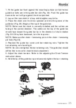
1. Fit the guide bar flush against the mounting surface so that the two
guide bar bolts are in the guide bar slot (Fig. 33). Push the guide bar
back as far as it will go against the drive sprocket.
2. Lay out the saw chain in a loop and straighten any kinks.
3. Place the chain over the drive sprocket and into the groove of the
guide bar (Fig. 39). Begin at the top of the guide bar.
NOTE: Make sure the chain is correctly installed and the cutters are
facing in the correct direction. The cutters on the top of the guide bar
should face toward the guide bar tip in the direction of chain rotation
(Fig. 38. If they face backward, turn the loop over.
NOTE: Make sure the chain – tensioning pin is in the chain – tensioning
pin hole (Fig 40).
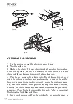
4. Replace the guide bar cover and bar-retaining nuts. Tighten the
bar-retaining nuts hand tight.
NOTE: Do not over-tighten the bar retaining nuts. The guide bar should
still be free to move for chain tension adjustment.
5. Adjust the chain tension. Refer to the adjusting the Chain Tension
instruction above.
6. Hold the tip of the guide bar up and securely tighten the bar- retaining
Fig. 32
Fig. 33
Fig. 34
Fig. 35
Fig. 36
Fig. 37


