
- 3 -
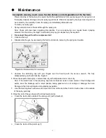
Instructions For Operation
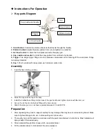
Key parts Diagram
1. Fluid Control
: Controls the volume ofmaterial that travels through the fluidtip.
2. Pattern Control
: Adjusts the spray pattern from a round pattern to a wide fan.
3. Air Flow Control
: Controls the fluid pressure inside the spray gun.
4. Cap, nozzle and needle
: Controls the spray pattern from vertical to horizontal.
5. Trigger
: Two stage trigger. Stage one only releases compressed air for blowing off the work piece. Stage
two sprays material.
6. Cup
: 125 ml cup allows for easy clean-up. Includes a vented cap
.
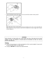
Assembly
1. Insert the filter into the gun body
2. Screw the cup onto the top of the body.
3. Install the barbed hose fitting into the base of the gun handle and tighten in place with the lock nut.
4. Secure the air hose to the barbed fitting with a hose clamp.
5. Attach the spray gun to an air hose regulated between 43.5 and 58 PSI .
Preparation
1. After unpacking the product, inspect carefully for any damage that may have occurred during transit. Make
sure to tighten fittings, bolts, etc., before putting unit into service.
2. Thoroughly mix and thin paint in accordance with the paint manufacturer
’s instructions. Most materials will
spray readily if thinned properly.
3. Strain material through filter, cheese cloth or a paint strainer.
4. Fill the canister about ¾ full and start the air compressor.
Cap, nozzle and needle
Cup
Fluid Control
Trigger
Air Flow Control
Pattern Control