14
•
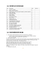
3.4.2. The parts list for the MIG GUN
NO.
Description
QTY.
Remark
1
Tip D.12 14-15AK
1
2
Electric nozzle 0.8/M6*25
1
3
15AK Goose gun neck (Hexangular adapter and Plastic adapter)
1
3.1
15AK Goose gun
1
4
Hexangular adapter
1
5
Plastic adapter
1
6
MIG blue handle
1
7
Torch Switch 21.8mm
1
8
Screw D.3*10
3
9
Handle locking ring
1
10
Cable fixing joint 15AK
1
11
Coaxial cable team /16mmq/3m
1
12
Cable thimble 12-16-25 MMQ
1
13
CO
2
Euro-rear thimble
1
14
Screw M4*6 UNI 6107
1
15
Torch locknut /plastic screw thread
1
16
Euro-main socket/flexibility pin
1
17
Feeding pipe locknut
1
18
Insulating feed pipe 0.6-0.8 3m, Blue
1
19
Spanner for the electric nozzle
1
•
3.4.3. The operation for the MIG GUN
1.
Service the wire feed mechanism at least every time the reel is changed.
-
Check the wear of the feed roll groove and change the feed roll when necessary.
-
Clean the welding gun wire guide with compressed air.
2.
Cleaning the wire guide
Pressure of the feed rolls remove metal dust from the filler wire’s surface which then finds its way
to the wire guide. If the wire guide is not cleaned, it gradually clogs up and causes wire feed
malfunctions. Clean the wire guide in the following manner:
Remove the welding gun’s gas nozzle, contact tip and contact tip’s adapter.
With a pneumatic pistol, below compressed air through the wire guide.
Blow the wire feed mechanism and reel housing clean with compressed air.
Reattach the welding gun’s parts. Tighten the contact tip and contact tip’s adapter to spanner
tightness.
3.
Changing the wire guide
Summary of Contents for 250MIG
Page 1: ...SERIES 250MIG MIG ...
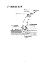
Page 10: ...10 2 4 Principles of welding ...
Page 16: ...16 4 OPERATION ...
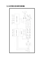
Page 23: ...23 5 3 ELECTRICAL SCHEMATIC DRAWING ...
Page 24: ...24 250MIG MIG ...


