8
Rollerdor RD20X2 Control Box, Edition 2022/1
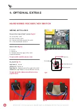
WIRING AS FOLLOWS:
Receiver Box Green 6 Block Terminal
(fig.15)
:
L0
– Up wire from switch
L2
– Down wire from switch
L1
– Common wire for the supply to the switch
L1
– L3 Link wire between terminals
Rocker Switch
(fig.16)
:
4
– Up wire
3
– Down wire
5
– Common wire for the supply to the switch
Fit Link wire from
5 to 2
To open rocker switch remove screws
Key Switch
(fig.17)
:
Right Block 13
– Up wire
Left Block 14
– Down wire
Right Block 14
– Common wire for the supply to the switch
Left Block 13
– Right Block 14 Link wire between terminals
To open key switch remove screw then turn key
a quarter turn.
HARD WIRED ROCKER / KEY SWITCH
fig.17B
fig.17A
4. OPTIONAL EXTRAS
fig.16
Pictures are for illustration purposes only, connector blocks are not provided and further fittings may be required.
fig.15
A
B
Link wire
Up wire
Down wire
Common wire


