background image

60

8. When Not in Use for a Prolonged Period

Keep Performing Maintenance

Switch on the power once every two weeks.

Switch on the sub power once every two weeks. When you turn on the power, the machine automatically 
performs some operations such as those to keep the print heads from drying out. Allowing the machine to 
stand completely unused for a prolonged period may damage the print heads, so be sure to switch on the 
power to perform these automatic operations.

Keep at a Constant Temperature and Relative Humidity

Even when the machine is not in use, keep it at a temperature of 5 to 40˚C (41 to 104˚F) and a relative humidity 
of 20 to 80% (with no condensation). If temperatures are too high or too low, it may cause malfunction.

Alarm Feature

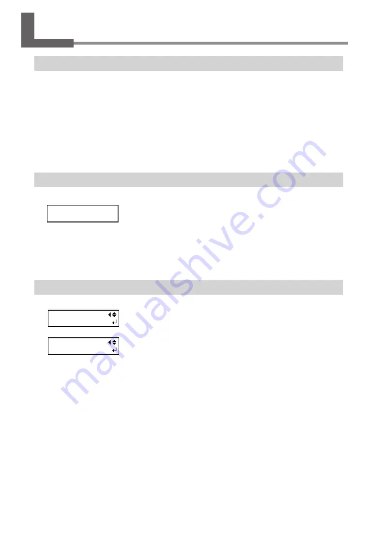
This feature is to remind you to switch on the sub power once a month. When 
the machine remains unused for about one month, this screen appears and a 
warning beep sounds. If this screen appears, switch on the sub power. When 
maintenance operations finish, switch off the sub power.
This feature operates when the printer's main power is turned on. We recom-
mend leaving on just the main power to the printer even when the machine is 
to remain out of use for a prolonged period

Important Note on Draining Ink

This machine has features for draining internal ink and for performing washing 
using SOL INK cleaning cartridges, but they should never be used except in special 
cases. Allowing the machine to stand without ink for a prolonged period may 
damage the heads, even if internal washing is performed. Once ink has been 
filled, then as a rule the ink should never be drained.

PRESS THE POWER

KEY TO CLEAN

INK CONTROL

PUMP UP

INK CONTROL

HEAD WASH

Summary of Contents for versaUV lec-540

Page 1: ...Setup Guide Read this first This describes the setup tasks and important conditions about the installation location that must be met in order to enable use of this machine...

Page 2: ...specifications of this product are subject to change without notice The documentation and the product have been prepared and tested as much as possible If you find any misprint or error please inform...

Page 3: ...2 35 Attach the Media Hold Down Unit and the Rigid Media Table 36 4 Connecting the Cables 42 Connecting the Cable of the Take up Unit 42 Connecting the Power Cord and the Network Cable 43 5 Installing...

Page 4: ...spect to the home and all its furnishings as well to domestic animals or pets About the Symbols The symbol alerts the user to important instructions or warnings The specific meaning of the symbol is d...

Page 5: ...ident Before attempting cleaning mainte nance or attachment or detachment of optional items disconnect the power cord Attempting such operations while the ma chine is connected to a power source may r...

Page 6: ...ings WARNING Handle the power cord plug and electri cal outlet correctly and with care Never use any article that is damaged Using a damaged article may result in fire or electrical shock When using a...

Page 7: ...on top or subject to damage Never bend or twist with undue force Never pull with undue force Never bundle bind or roll up Never allow to get wet Never make hot Dust may cause fire Important notes abou...

Page 8: ...n ink and their safety WARNING Keep open flame away from the work area Ink and discharged fluid are flammable Never store ink cleaning fluid or dis charged fluid in any of the following locations Any...

Page 9: ...s casters If the machine should begin to topple a ma jor accident may result including crushing of the appendages or the body When storing roll media implement adequate safety measures to ensure that...

Page 10: ...the cover move at high speed and pose a hazard Never insert the hand or fingers into the gap Caution Pinching Hazard Be careful not to allow the fin gers to become pinched when loading media or closi...

Page 11: ...tout autre effet ind sirable sur la maison tous les meubles et m me les animaux domestiques propos des symboles Le symbole attire l attention de l utilisateur sur les instructions importantes ou les a...

Page 12: ...mentation et autres articles semblables compatibles avec l appareil Les articles incompatibles risquent de causer des accidents PRUDENCE Faire preuve de prudence pour viter l crasement ou le coincemen...

Page 13: ...et causer un faux pas ou une chute ce qui causerait des blessures Risque de d charge ou de choc lectrique d lectrocution ou d incendie Caract ristiques ATTENTION Ne jamais ins rer d objet tranger dans...

Page 14: ...courant en cas de d faillance Placer l appareil de fa on ce que la fiche soit facile d acc s en tout temps Ainsi l appareil pourra tre d branch rapi dement en cas d urgence Installer l appareil pr s...

Page 15: ...la fiche ou sur la prise car cela risque de les endommager Ne jamais plier ni tordre le c ble avec une force excessive Ne jamais tirer sur le c ble ou la fiche avec une force excessive Ne jamais plie...

Page 16: ...TENTION Ne pas approcher une flamme nue de l espace de travail L encre et les liquides us s sont inflam mables Ne jamais entreposer d encre de liquide de nettoyage ou des liquides us s dans les endroi...

Page 17: ...crasement Le d chargement et la mise en place doivent tre faits par au moins six per sonnes Les t ches qui exigent un effort trop grand si elles sont ex cut es par un petit nombre de personnes peuvent...

Page 18: ...avec le corps Utiliser uniquement dans un endroit bien a r Attention Rayonnement ultraviolet Ne jamais regarder de pr s et directe ment pendant une p riode prolong e Attention T tes d impression mobi...

Page 19: ...Setup Guide 17...

Page 20: ...ion that is dark or cluttered may lead to an accident such as becoming caught in the machine as the result of an inadvertent stumble WARNING Position so that the power plug is within immediate reach a...

Page 21: ...itation of your eyes nose and throat To use this machine make sure to install ventilating equipment for adequate ventilation P 58 7 Installation of Ventilating Equipment During operation Temperature 2...

Page 22: ...roller 1 Stand leg left 1 Stand leg right 1 Rail slider 1 Paper tube 1 Shafts 2 Power cord 1 Arm Arm retaining Screw 1 of each Media holder Media holder retaining screw 1 of each for right and left S...

Page 23: ...slot labels 1 of each Cleaning sticks Cleaning fluid 1 Tweezers 1 Replacement wipers 6 Software RIP 1 User s Manual 1 Setup guide this document 1 White and Gloss Ink Guide 1 INKJET PRINTER MAIN TENAN...

Page 24: ...injury 1 Attach the left and right stand legs to the stand stay Place the stand stay on the accessories box Attach the stand stay to the right and left stand legs and secure them with bolts Loosely ti...

Page 25: ...Loosely tighten the bolts in the 8 locations shown in the figure Fully tighten all the loosely tightened bolts w Lower the levers of all the casters The casters are locked Remove the accessories box...

Page 26: ...th the tab on the stand leg Loosely tighten the bolts in the 2 location shown in the figure Loosely tighten the bolt on the stand leg right first Fully tighten all the loosely tightened bolts Please u...

Page 27: ...the location shown in the figure Align the bolt holes and loosely tighten the bolts Loosely tighten the bolt on the stand leg right first Fully tighten all the loosely tighten bolts Packing material D...

Page 28: ...rely As shown in the figure press down the top of the arm with your hand and tighten the arm retaining screw For the paper tube use the included item Using something other than the included item may r...

Page 29: ...l resulting in injury Procedure Place the machine on the stand Mount the machine aligning the holes on the under side of the machine with the projections on the top of the stand Loosely tighten the bo...

Page 30: ...aft Pass it through from the right edge as seen from the back of the machine Hook the media holder left on the shaft in the back w Move the left media holder to the left side of the shafts Attach the...

Page 31: ...e media holder right on the shaft in the back Attach the media holder retaining screw Only light tightening is necessary for the media holder retaining screw Attach the shaft clamps to the shaft The s...

Page 32: ...ling 30 Step 4 Attach the Media Guide Procedure Move the dancer roller toward the rear Remove the screws at the both ends Use a commercially available screwdriver Dancer roller Remove the screw Screw...

Page 33: ...near the center in 2 locations Hook the media guide on the loosened screws Tighten the screws The media guide is secured For the both ends use the screws that were removed in Engage Media guide Engag...

Page 34: ...side of the machine for storage Procedure Remove the drain tube cover Secure the bottle stand in place Using the bolts that held the drain tube cover in place secure the bottle stand in place Remove t...

Page 35: ...the machine attach the drain bottle At the location shown in the figure secure in place the part you removed in step Fasten using the bolt provided which is attached to the underside of the machine B...

Page 36: ...all packing materials Any that remain may cause faulty operation or breakdown when the power is switched on Store the packing materials carefully because they are needed again when transporting the m...

Page 37: ...3 Assembling and Installing 35 Step 7 Attach the Front Cover 2 Attach the front cover 2 Make sure you secure the front cover 2 with the retaining screws Front cover 2...

Page 38: ...r climb or lean on the media hold down unit or the rigid media tables They are not made to support a person Climbing or leaning on the rigid media tables may dislodge components and cause a slip or fa...

Page 39: ...3 Assembling and Installing 37 v Attach the front cover 2 to the media hold down unit Make sure you secure the front cover 2 with the retaining screws Front cover 2 Not OK Not OK OK OK...

Page 40: ...a table as shown in the figure Raise the media carrier section as far as it will go then lower it slightly to lock it into place Collapsing the Media Carrier Section When the media carrier section is...

Page 41: ...embling and Installing 39 CAUTION Pinching hazard Use care to avoid pinching fingers when collapsing the rigid media tables Hold this part when collapsing the table Hold this part when collapsing the...

Page 42: ...and right sides of the rigid media table and hook them onto the pins When attaching the rigid media table to the front of the machine hook the hooks onto the pins on the media hold down unit Front of...

Page 43: ...3 Assembling and Installing 41 y Lower the levers of all the casters The casters are locked Caster Lower...

Page 44: ...ting the Cables Connecting the Cable of the Take up Unit Peel off the tape Pass the take up unit cable through at the locations shown in the figure and connect it Tape Cable clamp Take up unit cable T...

Page 45: ...cause fire or electrical shock WARNING Connect to ground This can prevent fire or electrical shock due to current leakage in the event of malfunction WARNING Perform this task with all power switches...

Page 46: ...and black 2 cartridges of gloss The EUV EUV3 EUV4 ink White mode 1 cartridge each of cyan magenta yellow and black 2 cartridges of white Gloss White mode 1 cartridge each of cyan magenta yellow black...

Page 47: ...ode Hold down and on the operation panel and switch on the main power switch When the message shown below appears on the display screen release the oper ation panel buttons SET INK MODE CMYKGlW SET IN...

Page 48: ...ink mode Go on to the next step Affixing the Cartridge slot Labels Affixing the Cartridge slot Labels Procedure Open the ink cartridge cover At the locations shown in the figure affix the cartridge s...

Page 49: ...Cartridges 47 Ink mode Gloss mode Cartridge slot labels to affix After affixing Ink mode White mode EUVS ink mode Cartridge slot labels to affix After affixing Ink mode Gloss White mode Cartridge slot...

Page 50: ...ment you want for length Press Use to select the unit of measurement you want for temperature Press Insert each color ink cartridge into the slot labeled with the matching color If you insert wrong ca...

Page 51: ...W When the selected ink mode is enabled Go on to the next step When an incorrect ink mode is enabled Switch off the sub power Again carry out the procedure on P 44 Selecting the Ink Mode Press to sele...

Page 52: ...idges Insert the SOL INK cleaning cartridges you pulled out into slots 5 and 6 When this screen appears pull out the SOL INK cleaning cartridges When this screen appears cleaning is finished Make sure...

Page 53: ...onds If ink components precipitate it will not be possible toprintwithcorrectcolors Sothattheinkmixeswell shake each ink cartridge horizontally with a stroke lengthofaround5cm 2in fromeachendoftheink...

Page 54: ...kcartridgecoverpreventstheinkcartridgesfrombeingexposedtodirectsunlightorstrongillumination If the ink cartridges are exposed to them the ink inside the cartridges will become hardened and it may caus...

Page 55: ...ing one computer and one machine The procedures and setting values described here may not be suitable for all operating environments If the computer you re using is connected to a number of networked...

Page 56: ...Use the following IP address Enter the infor mation as shown below and then click OK Item Address to enter IP address 192 168 0 XXX Subnet mask 255 255 255 0 Here XXX can be any number from 1 to 254...

Page 57: ...esuretoeliminatethenumberoverlappingwiththesettingyou made in Step 1 Here 192 168 000 003 shall be entered as an example For the part corresponding to 192 168 000 apply the same value as the setting o...

Page 58: ...the procedure following this one 3 Set the gateway address From the screen displayed in 1 press twice v Press twice w Use to select the address number GATEWAY ADDR 255 255 255 255 For the value to ent...

Page 59: ...he IP address set for the machine For the setup procedures refer to the documentation of the instructions for the software RIP You can check whether the connection to the network has been complete by...

Page 60: ...G Corp dealer You will need a hose to connect the ventilating equipment and this machine The connecting port diameter 38mm P 19 Air Ventilation Installing the Ventilating Equipment Note The 3 mm hexag...

Page 61: ...7 Installation of Ventilating Equipment 59 w Attach the hose to the connection port on the unit Insert all the way Connecting port Diameter of 38 mm 1 5 inches...

Page 62: ...eature This feature is to remind you to switch on the sub power once a month When the machine remains unused for about one month this screen appears and a warning beep sounds If this screen appears sw...

Page 63: ...a temperature between 5 to 40 C 41 to 104 F and at relative humidity between 20 to 80 with no condensation Failure to do so may result in breakdown Handle the machine with care when moving keeping it...

Page 64: ...tains toxic ingredients Never attempt to incinerate discharged fluid or discard it with ordinary trash Also do not dispose of it in sewer systems rivers or streams Doing so may have an adverse impact...

Page 65: ......

Page 66: ......

Page 67: ......

Page 68: ...R3 160719...

Reviews: