


14
May 2002
3.
Connect MIDI OUT of the sequencer and MIDI IN of the MC-09 with the
MIDI cable.
Beyond these steps, proceed according to the updating mode.
Procedure for ALL Updating
Mode
1.
While holding down the [SEL] buttons of parts 1, 2 and 4 of AUDIO
LOOPER, “ALL” appears on the display when the power is turned on.
2.
Load the SMF data [UP_A_TKO.MID] from the sequencer.
3.
“Ers” appears on the display and the Flash Memory is
initialized.Approximately 10 seconds later, “UPd” appears on the
display.(Do not load the data while “Ers” is displayed.)4. Load the SMF
data for updating from the sequencer.Playback the 12 [_TKO00.MID] -
[_TKO11.MID] files in numerical order.
4.
While loading the data, the LED of the [START] button blinks and the
number displayed is incremented.
5.
When all files have been loaded, “End” appears on the display to indicate
completion of updating. Approximately 10 minutes is required for
loading all of the SMF files.
6.
After completion of updating, turn on the main power again, enter the
test mode, confirm the version and conduct a device check. Subsequently,
conduct factory reset.
Procedure for USER Update Mode
1.
While holding down the [SEL] buttons of parts 1, 3 and 4 of AUDIO
LOOPER, “USR” appears on the display when the power is turned on.
2.
Load the SMF data [UP_U_TKO.MID] from the sequencer.
3.
“Ers” appears on the display and the Flash Memory is
initialized.Approximately 10 seconds later, “UPd” appears on the
display.(Do not load the data while “Ers” is displayed.)
4.
Load the SMF data for updating from the sequencer. Playback the 11
[_TKO01.MID] - [_TKO11.MID] files in numerical order.
5.
While loading the data, the LED of the [START] button blinks and the
number displayed is incremented.
6.
When all files have been loaded, “End” appears on the display to indicate
completion of updating.
7.
After completion of updating, turn on the main power again, enter the
test mode, confirm the version and conduct a device check. Subsequently,
conduct factory reset.
Actions to be Taken when the
Unit became Unrebootable
Turning off the power accidentally while update may cause improper booting
of the unit.
1.
Replace the board if booting becomes impossible after ALL update.
2.
Repeat the USER updating procedure again if the unit becomes
unrebootable after USER update.
List of Error Messages Displayed
upon Updating
Er0:Erase Error
Displayed when contents of the Flash Memory cannot be initialized. It is
assumed that the power is not supplied to the VPP terminal of the Flash
Memory.
Er1:Write Error
Displayed when an error occurs while trying to write the Flash Memory.
Er2:Message Error
Displayed when a problem exists in received MIDI message. (SumCheck, etc.)
Er3:FIFO Over Flow
Displayed when the MC-09 cannot process a large amount of MIDI messages
received all at once.
Er4:Overrun Error
Displayed when a MIDI message is missed.
Er5: Framing Error
Displayed when a problem exists in the received MIDI message data such as
transfer rate and jitter.
Er6:Compare Error
Displayed when a difference is found upon comparison of data written in the
Flash Memory and data to be written to the Flash Memory.
TEST MODE
Devices to be Used
MIDI cable x 1
Oscillator
Noise meter
Oscilloscope
Audio cable
Smart Media Card
Method of Booting in the Test
Mode
While holding down [SHIFT] and Step [4], turn on the main power.
Automatically proceeds to version display of item 1.
*
Selection of Test Items Proceed through the items in the test mode by holding
down [SETUP] and [TAP]. Moreover, holding down [SETUP] and Step [Item
Number] proceeds directly to
the desired inspection item.
Details on Each Test Item
1:Version Display
Displays the program version on the display.
Ex: “1.03” appears on the display when the version is 1.03.
*
Holding down [SETUP] and [TAP] proceeds to the next item.
2:Device Test
Performs an operation check on each device (IC).
Insert the Smart Media Card (voltage: 3.3V, capacity: 2-128MB) into the
memory card slot beforehand.
“DEV” appears on the display and checking in the following order
automatically starts:
Step [4] will light if ESP RAM (IC1) is O.K.
Step [2] will light if WORK RAM (IC3) is O.K.
Step [3] will light if EEP RAM (IC6) is O.K.
Step [5] will light if Smart Card is O.K.
Step [1] will light if Flash ROM (IC8) is O.K.
Requires approximately one minute to complete.
“ok” appears on the display when all are confirmed to be O.K.
If an error occurs, the error number appears on the display and procession to
the next item is disabled.
Summary of Contents for Phase Lab MC-09
Page 3: ...3 MC 09...
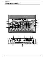
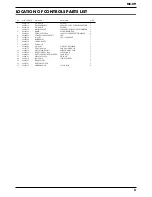
Page 4: ...4 May 2002 LOCATION OF CONTROLS fig top...
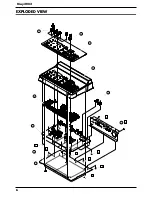
Page 6: ...6 May 2002 EXPLODED VIEW fig explo 1 8 2 9 4 5 6 10 7 a b b c c c c c b 3...
Page 11: ...11 MC 09...
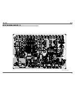
Page 17: ...19 May 2002 MC 09 CIRCUIT BOARD MAIN BOARD 1 2 fig block View from component side...
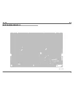
Page 18: ...21 May 2002 MC 09 CIRCUIT BOARD MAIN BOARD 2 2 fig block View from foil side...


