background image

3-8 Starting Printing

Chapter 3 Performing Printing

42

Stopping Printing Operations

Procedure

Switch off the power.

 P. 24, "Switching Off the Power"

Windows Vista
Click [Start], then click [Control Panel].
Click [Hardware and Sound], then click [Printers].
Windows XP
Click [Start], then click [Control Panel].
Click [Printers and Other Hardware], then click [Printers and Faxes].
Windows 2000
Click [Start].
Click [Settings], then click [Printers].

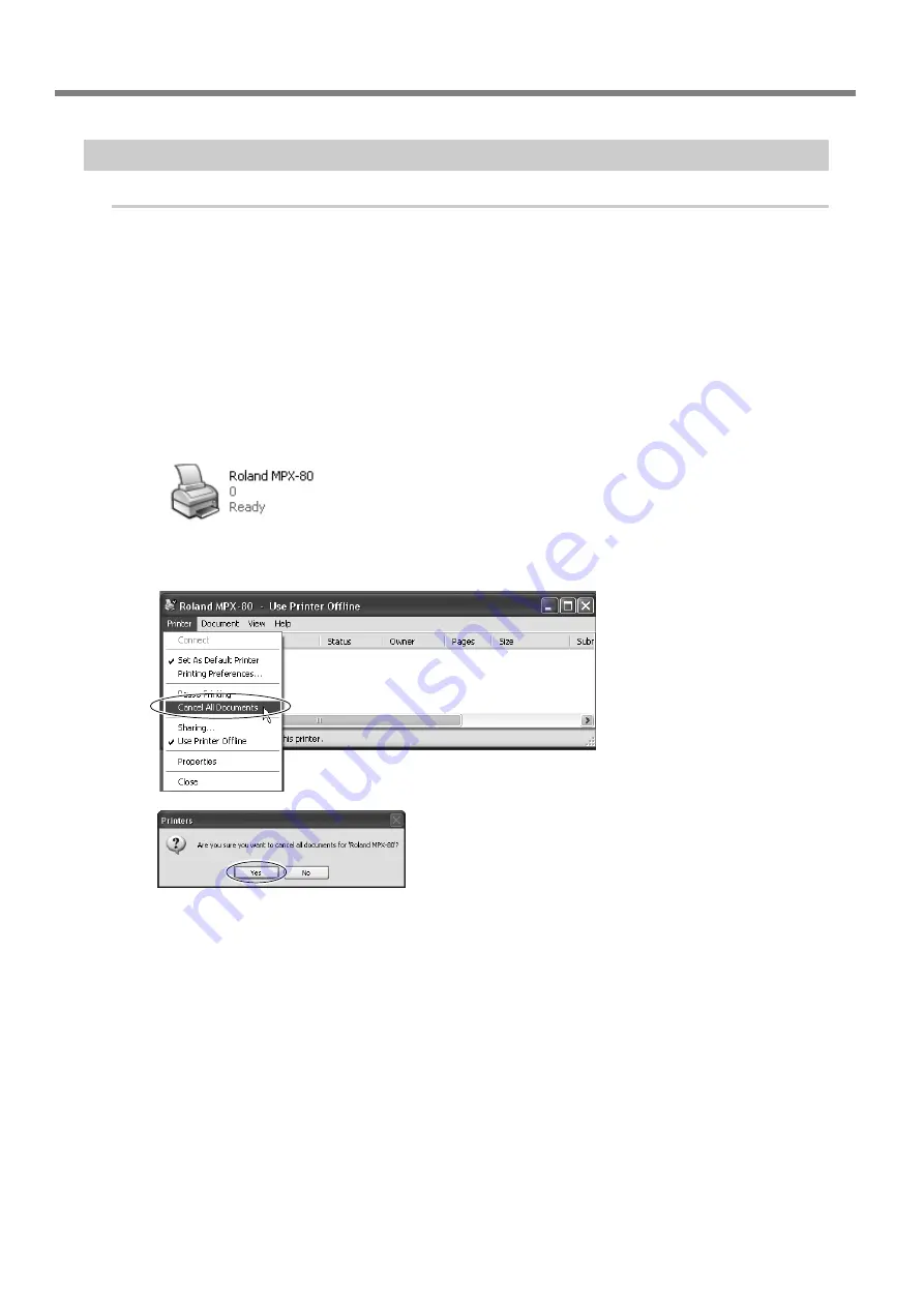
Double-click the [Roland MPX-80] icon.

At the [Printers] menu, click [Cancel All Documents] (or [Purge Print Documents]).

If the message shown in the figure appears, click
“Yes.”

Summary of Contents for Metaza MPX-80

Page 1: ...d DG Corp is prohibited The contents of this document and the specifications of this product are subject to change without notice Roland DG Corp assumes no responsibility for any loss or damage relating to this product regard less of any defect in this product or this manual Such loss or damage whether direct or indirect includes but is not limited to that arising from the specifications or perfor...

Page 2: ...mits are designed to provide reasonable protection against harmful interference when the equipment is operated in a commercial environment This equipment generates uses and can radiate radio frequency energy and if not installed and used in accordance with the instruction manual may cause harmful interference to radio communications Operation of this equipment in a residential area is likely to ca...

Page 3: ...25 Names and Functions of METAZAStudio Screen Items 26 3 3 Getting Ready to Print 27 The Printable Area 27 Head Caps 27 Preparing Material to Print 28 Preparing the Image 30 3 4 Loading Material Using the Adhesive Sheet 31 Loading Material Using the Adhesive Sheet 31 Handling of the Adhesive Sheet 32 3 5 Loading Material Using the CenterVise 33 Using the Center Vise 33 Loading Material Using the C...

Page 4: ...at s SFEdit2 66 Starting SFEdit2 66 Chapter 5 Maintenance and Adjustment 67 5 1 Daily Care 68 Daily Care 68 Cleaning the Adhesive Sheet 68 Cleaning the Body and Cover 68 The Replacement Cycle for the Head Cap 69 5 2 Maintenance of the Head and the Marking Pins 70 Starting MPX 80 Head Manager 70 Head Cleaning 71 Checking the State of the Marking Pins 72 Changing the Pin Used for Marking 73 Adjustin...

Page 5: ...ngs that must be carried out The specific thing that must be done is indicated by the design contained within the circle The symbol at left means the power cord plug must be unplugged from the outlet To Ensure Safe Use Improper handling or operation of this machine may result in injury or damage to property Points which must be observed to prevent such injury or damage are described as follows Inc...

Page 6: ... be a danger Danger of electrical short shock electrocution or fire Handle the power cord plug and electri cal outlet correctly and with care Never use any article that is damaged Using a damaged article may result in fire or electrical shock When using an extension cord or power strip use one that adequately satisfies the machine s ratings for voltage frequency and current Use of multiple electri...

Page 7: ...the power cord plug and electrical outlet Never place any object on top or subject to damage Never allow to get wet Never bend or twist with undue force Never make hot Never pull with undue force Dust may cause fire Never bundle bind or roll up ...

Page 8: ...To Ensure Safe Use 6 The head area becomes hot WARNING Never touch the head immediately after printing has finished Doing so may cause burns ...

Page 9: ...bel is affixed to make areas of danger immediately clear The meaning of the label is as follows Be sure to heed its warnings Also never remove the label or allow it to become obscured Caution HighTemperature Never touch immediately after printing ...

Page 10: ...ity Install in a quiet stable location offering good operating conditions When Moving the Machine When moving the machine be sure to support it at the bottom using two hands Attempting to move the machine by holding it at a different location may result in damage When moving the machine to another location be sure to attach the retainers Attempting moving without attaching the retainers may result...

Page 11: ...ing Be sure to read it first Roland Software Package Software Guide This explains how to install included program and other software and details Be sure to read this when connecting the machine to a computer Windows Driver Online Help Roland METAZAStudio Online Help Roland SFEdit2 Online Help You view this documentation on your computer screen Installing the respective programs makes these availab...

Page 12: ...10 ...

Page 13: ...11 Chapter 1 Getting Started ...

Page 14: ...Chapter 1 Getting Started 12 1 1About the Machine Features This machine is a metal printer It prints images by striking detailed points using a marking pin mounted in a head ...

Page 15: ... of the table Pressing it a second time moves the head to the inte rior left and the table back to the front edge of the unit To switch off the power you hold down the button for one second or longer Table Knob This secures the head unit and determines the head height when performing printing with out using a head cap Cover USB connector Power code connector Brush Head unit This moves up and down ...

Page 16: ...Adhesive Sheet Center vise This is a vise made of plastic and secures material in place by clamping it This makes it possible to immobilize material that can not be secured using the adhesive sheet such as items having a curved bottom surface The act of securing an item in place also accu rately determines the center position in the horizontal direction P 33 Loading Material Using the CenterVise M...

Page 17: ...the machine Make sure they are all present and accounted for Power cord Roland Software Package CD ROM USB cable AC adapter Adhesive sheet installed on the unit by default Center vice Software Guide User s manual this document Test use printing material Head caps one installed on the unit by default ...

Page 18: ...16 ...

Page 19: ...17 Chapter 2 Getting Ready to Print ...

Page 20: ...cident including a fall or tipover Never install in a location subject to wide fluctuations in temperature or humidity Never install in a location subject to shaking or vibration Never install in a location where the floor is tilted not level or unstable Never install in a dusty or dirty location or out of doors Never install in a location exposed to direct sunlight or near air conditioning or hea...

Page 21: ...the power is switched on The Retaining materials are required when moving the machine to a different location Store them carefully so that they do not get misplaced Procedure Open the cover Loosen the knob Remove the retaining screw and store it at the location shown in the figure Remove retainer A Holding the unit at the locations shown in the figure lift the head unit and re move retainer B Rola...

Page 22: ...ver use any article that is damaged Using a damaged article may result in fire or electrical shock WARNING When using an extension cord or power strip use one that adequately satisfies the machine s ratings for voltage frequency and current Use of multiple electrical loads on a single electrical outlet or of a lengthy extension cord may cause fire Never connect two or more machines to one computer...

Page 23: ...river Roland METAZAStudio Roland SFEdit2 MPX 80 Head Manager For overviews of the programs and other software and more information on how to install them refer to the separate Roland Software Package Software Guide For METAZAStudio after installing the program the setting for the printer to use must be made For information on how to make the setting refer to METAZAStudio Settings on the following ...

Page 24: ...io continue by making the setting for the printer Be sure to make the setting before use Procedure Click Start then click All Programs or Programs Click Roland METAZAStudio then click METAZAStudio Go to the File menu and click Set up the printer The Print Setup dialog box appears Click the arrow shown in the figure then select Roland MPX 80 Click OK ...

Page 25: ...23 Chapter 3 Performing Printing ...

Page 26: ... head and table move as follows Head This rises to the highest position then moves to the left edge Table This moves to the interior of the machine then back to the front This operation is called initialization Switching Off the Power Hold down the Power Movement button for one second or longer The light goes dark and the power is switched off Power Movement button ...

Page 27: ...Studio Starting METAZAStudio Click Start then click All Programs or Pro grams Click Roland METAZAStudio then click METAZAStudio After the opening screen the screen for METAZAStudio appears For information on how to view this window see the following page ...

Page 28: ...two centerlines intersect is 0 0 Centerline This indicates the vertical center lo cation of the window Table The unit s table is shown here The scale displayed represents the actual scale marks on the table Work Area This is the area in which printing is possible The workpiece size printing area set with the Windows based driver is shown here P 64 Driver settings Grid Pitch This displays the pitch...

Page 29: ...head cap P 29 Conditions for Material When Printing Curved Surfaces p 69 The Replacement Cycle for the Head Cap If the material is damaged when using the head cap Some materials may be damaged by the head cap and so the head cap cannot be used when printing such materials In such cases determine the head height while the head cap is attached and secure the head in place then remove the head cap an...

Page 30: ...nted even if hardness is within the preceding range Attempting to print such materials may damage the machine Preparing Material to Print Prepare material that meets all of the following conditions Loading material that is larger or thinner than this may cause the material to warp during printing and strike the head damaging the marking pin Thickness 2 0 mm 0 08 in 1 5 mm 0 06 in 1 0 mm 0 04 in 0 ...

Page 31: ...mm 0 079 in 2 8 mm 0 11 in 20 mm 0 7 in 2 8 mm 0 11 in 4 0 mm 0 16 in 30 mm 1 1 in 3 4 mm 0 14 in 4 8 mm 0 19 in Marking depth to which printing can be assured Depth reached by the marking pins Note For printing on curved surfaces regardless of the shape or composition of the material the image quality of photographic data cannot be assured Cross section of printing material Back surface is curved...

Page 32: ...TAZAStudio Files in JPEG format Files in BMP bitmap format Files in AI or EPS format created by Illustrator version 7 or 8 Files in AI or EPS format exported by CorelDRAW version 7 or 8 Note Illustrator and CorelDRAW files are subject to a number of limitations For details see the online help for METAZAStudio METAZAStudio online help Hints and Tips Reusing Existing Data ...

Page 33: ...l to secure it in place If you re performing printing with the head cap attached this completes loading of the material If you re performing printing with no head cap attached then go on to the following steps Mounting the Adhesive Sheet Place it straight aligned with the scale marks on the table Place inside the table frame Be careful not to allow any air bubbles to form between the adhesive shee...

Page 34: ...cure it in place at a position flush against the head unit Press the Power Movement button Wait for the movement of the head to stop then detach the head cap Handling of the Adhesive Sheet Buildup of dust or the like on the adhesive sheet can reduce the sheet s adhesive force making it difficult to secure material in place If the adhesive force has been reduced then wash the adhesive sheet P 68 Cl...

Page 35: ...position of the machine s table For the vertical center position you perform adjustment using the scale on the vise as a guide You can also vary the orientation of the vise when using it Use it in a way matched to the size and shape of the material P 28 Preparing Material to Print Correspondence Between the CenterVise Scale and theTable Scale Vice You can also install it with the front and back re...

Page 36: ...nto place in the hole in the head P 27 Head Caps Loosen the knob Load the material in the center vise Adjust the retaining screw to clamp the ma terial in place in the vise Tighten the retain ing screw enough to keep the material from easily coming loose Be careful not to over tighten because doing so may damage the material P 33 Using the CenterVice Knob Head cap Head cap Retaining screw Center i...

Page 37: ...h no head cap attached then go on to the following steps The procedure from this point on is for when you re not using the head cap Press the Power Movement button The table and head move and stop at the lo cation where the tip of the nose cap touches the surface of the material Lock the knob to set the head height Gently lift the knob then secure it in place at a position flush against the head u...

Page 38: ...e on the material to print METAZAStudio has a number of different types of material preregis tered Here let s try using the material with the tag name which has the same shape as the plate used in the example a width of 25 millimeters and a height of 40 millimeters If you want to register new material see here P 62 How to Register New Material Procedure Click The Material window appears Click the ...

Page 39: ...ars Set Margin to 1 mm This is set at 1 millimeter by default Click OK Important For printing on a flat plate make the margin at least one millimeter Otherwise the marking pins may strike and damage the edge of the material Step 2 Import the Image Here you import the image to print Prepare an image file to import P 30 Preparing the Image Procedure Click The Import dialog box appears ...

Page 40: ...g its size or orientation or by adding borders around it P 44 Tips and Tricks for Image Layout Important If the material has holes take care to ensure that the image is not laid out over the holes Making an area with a hole the printing area may cause the marking pins to strike and damage the edge of the material P 45 Adjusting the Location Size or Angle of an Image 1 mm 1 mm Printing area The pri...

Page 41: ...inting on Flat Material Chapter 3 Performing Printing 39 Step 3 Save the File Save the printing data in a file Procedure Click The Save As dialog box appears For Save in specify where to save the file Type in a file name Click Save ...

Page 42: ... Sheet p 33 Loading Material Using the CenterVise Procedure Close the cover Click The Print Setup dialog box appears Make sure Roland MPX 80 is cho sen as the printer name Click Properties Click the Image Correction tab Select Material Select either the composition or the prod uct code of the material Click OK Selection of the Material When you select the composition of the loaded material printin...

Page 43: ...s After printing has finished open the cover and detach the material If the Material Is Difficult to Detach When Using the Adhesive Sheet If the material is difficult to detach inserting a thin flat object such as a piece of stiff paper or cardboard between the adhesive sheet and the material may make it easier to dislodge ...

Page 44: ...ol Panel Click Hardware and Sound then click Printers Windows XP Click Start then click Control Panel Click Printers and Other Hardware then click Printers and Faxes Windows 2000 Click Start Click Settings then click Printers Double click the Roland MPX 80 icon At the Printers menu click Cancel All Documents or Purge Print Documents If the message shown in the figure appears click Yes ...

Page 45: ...43 Chapter 4 More Advanced Operations ...

Page 46: ...This operation is called trimming In this example you use the printing data created at page 36 Creating Printing Data Printing on Flat Material P 36 Creating Printing Data Printing on Flat Material Procedure Click Click the image Eight handles for trimming appear around the image Drag the trimming handles to determine the area to trim Adjust this to enable selection of the image area you want to k...

Page 47: ... to achieve the layout you want In this example you use the printing data created at page 44 Keeping Only the Required Portion of an Image Trimming Procedure Adjust the location Click then click the image Handles appear at the four corners of the image Drag the image to adjust its location Adjust the size Drag the handles at the four corners of the image to adjust the size Handles ...

Page 48: ...es to a pointer for rota tion Drag to adjust the angle slant of the image You can change the angle by up to 360 degrees Trimming cannot be performed for an image whose angle has been changed To perform trimming first return the image to its origi nal angle Holding down the keyboard s SHIFT key as you drag makes the angle change by 45 de grees at a time Using this method can be convenient at times ...

Page 49: ...gistered frames and you can also register new ones In this example you add a frame to the printing data created at page 45 Adjusting the Location Size or Angle of an Image For information on how to use the library see here Register often used shapes and images in advance on the page 63 A Wide Variety of OperationsYou Can Accomplish with METAZAStudio Procedure Click The Library window appears From ...

Page 50: ...just its size and location Adjust the location and size so as to enclose the image The adjustment methods are the same as the methods for adjusting the loca tion and size of an image P 45 Adjusting the Location Size or Angle of an Image Adjust the layout by changing the location or size of the image and the frame Handles Frame ...

Page 51: ...Chapter 4 More Advanced Operations 49 4 2Tips andTricks forText Layout Enter theText Here you type in the text to print Procedure Click Click somewhere on the material then type in the text ...

Page 52: ... fan layout Procedure Enter text P 49 Enter the Text Arrange the text horizontally Click The Properties dialog box appears Click the Format tab Select the Align with Curve check box Click OK The layout of the text changes to a fan shape You can adjust the size and position of the laid out text or change its format P 51 Adjusting Laid out Text p 55 Changing the Format of Text ...

Page 53: ...also change the type of fill used P 45 Adjusting the Location Size or Angle of an Image Procedure Enter text P 49 Enter the Text Click Click the laid out text Eight handles appear around the text Adjust the size Drag the handles to adjust the size Adjust the angle Click on the text The shape of the handles changes to Line up the pointer with a handle The shape changes to a pointer for rota tion Po...

Page 54: ...ox appears Click the Fill and Contour tab Select Island Fill Click OK The way the text is filled changes to spaced lines instead of solid color Increasing the value of Pitch enlarges the spacing be tween the lines Holding down the keyboard s SHIFT key as you drag makes the angle change by 45 de grees at a time Using this method can be convenient at times such as when you want to perform rotation b...

Page 55: ... drawing tools Procedure Click a drawing tool In this example you use In the editing window create a shape on the material For detailed information about the drawing tools see here METAZAStudio online help Commands Toolbar But tons Click Position the pointer near the outline of the shape you created and when appears under the pointer then click Drawing tools ...

Page 56: ...is laid out along the shape Important Layout on an integrated polyline is not possible METAZAStudio online help Commands Object menu Convert to Polyline Integrate Plylines You can adjust the size and position of the laid out text or change its format P 51 Adjusting Laid out Text p 55 Changing the Format of Text ...

Page 57: ...t ofText In the Properties window at the Format tab you can change such properties as the font of laid out text as well the height and width of the characters For detailed information about the settings refer to the online help for METAZAStudio METAZAStudio online help Commands Format menu ...

Page 58: ...ng the Finished Results in the PreviewWindow At the preview window you can adjust the brightness contrast and gamma correction An image with clearly defined light and dark areas produces attractive printed results Adjust to match the image Click Preview window appears Preview window ...

Page 59: ... want to achieve a sense of tension with a good balance of light and dark Gamma This mainly adjusts the brightness of tones of intermediate brightness between bright and dark areas Using it is effective in ad justing the overall brightness The dark and bright areas are printed as shown in the figure Dark color areas are not struck and light color areas are struck forcefully Also the printing resul...

Page 60: ...For this reason the METAZAStudio editing window displays the printing area instead of the material The printing area is determined by the value of the material s diameter entered at the setting window for the driver For more information about the conditions of cylindrical material that this machine can print refer to the page indi cated below P 29 Conditions for Printable Cylindrical Material Proc...

Page 61: ...X 80 is choosen as the printer name Click Properties Make the Diameter and Material Ori entation settings for the cylindrical material Click the Material tab Set Diameter to 10 millimeters Select Direction In this example select vertical Click Enter Under Work Size the value for Width is set automatically For Length in this example make the setting of 50 millimeters Click OK Click OK ...

Page 62: ...terText and Adjust the Layout Type in the text to print then adjust how it s laid out Procedure Enter a single character of text in the printing area P 49 Enter the Text Arrange the text in a vertical orienta tion then adjust it so that it fits within the printing area P 51 Adjusting Laid out Text ...

Page 63: ...tions 61 Enter text remained and adjust the po sition The on screen table scale corresponds to the scale for the center vise as shown in the figure Carefully adjust the positioning to enable the text to be printed at the location you want P 33 Loading Material Using the CenterVise ...

Page 64: ...f an image of the material is available you can import the image Note however that only bitmap data can be used Other requirements are as follows File format Must be either BMP bitmap or JPEG Number of colors Binary black and white portions corresponding to the material must be black filled Scanning the material with a scanner When no image of the material is available or the shape of the material...

Page 65: ...in advance You can register often used and generic use shapes in the library which enables you call them up and add them to your data whenever you need them Registering logos and other graphics can add convenience You can also register images METAZAStudio online help Hints and Tips Making Use of Library Create contour lines from images You can print imported images with added contour lines The dat...

Page 66: ...art then click Control Panel From the Hardware and Sound group click Printers Windows XP Click Start then click Control Panel Click Printers and Other Hardware then click Printers and Faxes Windows 2000 Click Start Click Settings then click Printers Right click Roland MPX 80 Click Printing Preferences The setting window appears About the Setting Window Going to the METAZAStudio File menu and click...

Page 67: ...line Help for the Driver For detailed information about the values you can set using the driver see the online help for the driver To view the online help for the driver go to the driver s setting window and click the Help button P 9 About the Documentation for This Machine ...

Page 68: ... fonts including creating and editing them refer to the online help for SFEdit2 P 9 About the Documentation for This Machine Starting SFEdit2 You can start SFEdit2 using either of two methods One is to run it from the Start menu in Windows The other method is to start it from the menu in METAZAStudio Running the Program from the Start menu in Windows Click the Start button then click All Programs ...

Page 69: ...67 Chapter 5 Maintenance and Adjustment ...

Page 70: ...sive sheet declines then wash the sheet Never scrub the adhesive sheet using a scrubbing pad or sponge Never stretch or bend the adhesive sheet when washing it How to Wash and Dry Immerse the adhesive sheet in water and wash the sheet by gently stroking its surface After washing allow to dry completely out of direct sunlight It must not be mounted on the table while wet If the Adhesive Sheet Gets ...

Page 71: ...r the Head Cap The head cap is due for replacement when the triangle at its tip see the figure below is worn away Replace it with a new head cap P 31 Loading Material Using the Adhesive Sheet p 33 Loading Material Using the CenterVise Replace when this triangle disappears Head cap ...

Page 72: ...ne s head has nine pins Printing is performed using these pins one at a time If the tip of the pin in use becomes worn you can change the pin used for printing You can also perform adjustment to ensure that each pin uses the same striking force Starting MPX 80 Head Manager Click Start then click All Programs or Programs Click MPX 80 Head Manager then click MPX 80 Head Manager Switch on the power t...

Page 73: ...way any fine grime around the head Perform cleaning periodically Procedure Detach the center vise or the adhesive sheet and loosen the knob Start MPX 80 Head Manager P 70 Starting MPX 80 Head Manager Click Cleaning Click OK The head moves and cleaning is performed Roland Detach the center vise or adhesive sheet ...

Page 74: ...tive printing is impossible or printed images are uneven even though the scale is not red then change to a new pin This indicates the amount of pin usage The indicator display increases a little at a time as striking is per formed The rate of increase varies according to the material printed Pins for which nothing is displayed are unused A pin needs to be replaced when it is shown in red This refr...

Page 75: ...pter 5 Maintenance and Adjustment 73 Changing the Pin Used for Marking Follow the steps below to change the marking pin Procedure Start MPX 80 Head Manager P 70 Starting MPX 80 Head Manager Choose the number of the pin to use next Click Apply Pin Change ...

Page 76: ...nager P 70 Starting MPX 80 Head Manager Click Readjust Pins Follow the on screen instructions to perform adjustment for the pins When you have finished click X The window closes How to Determine the AdjustmentValues For the adjustment value use the letter and number of the location where the value that can be read is lightest If this is difficult to determine decide on an appearance darkness to se...

Page 77: ...p dealer Procedure Never quit the replacement operation while partway through The head is a consumable part Never use a head whose marking pins are all worn out Never reuse a head once it has been removed Never use it a second time even if it contains unused pins Start MPX 80 Head Manager P 70 Starting MPX 80 Head Manager Click Replace Head Follow the on screen instructions to carry out head repla...

Page 78: ...sive Sheet p 33 Loading Material Using the CenterVise Start METAZAStudio Go to the File menu and click Open For Look in select the Samples folder in the METAZAStudio folder The folder where METAZAStudio is in stalled Select Axis dmz Click Open Start printing 2 Measure and type in the correction values Measure and note down the offset between the centerline on the table scale and the crossed lines ...

Page 79: ...rinters The Printers folder opens Right click Roland MPX 80 Click Printing Preferences The setting window appears Click the Material tab In the width and length fields for Offset enter the displacement values you noted in step 1 Click OK The window closes Entry of Correction Values When the setting window for METAZAStudio is displayed the values for any settings made there are temporary and are no...

Page 80: ...heir appropriate striking forces but you can also register compositions and their optimal striking forces yourself You can also carry out later adjustment of the striking force of compositions you ve registered yourself in order to obtain better printing results Procedure WindowsVista Click Start then click Control Panel From the Hardware and Sound click Printers Windows XP Click Start then click ...

Page 81: ...composition and a striking force appropriate for it To obtain printing result of even higher quality carry out test printing and overprinting on the same material and adjust the impact values while examining the printing results Raise When dark areas of the image are not struck Lower When dark areas of the image are whitish too bright When overall striking is too forceful Raise When bright areas o...

Page 82: ...80 ...

Page 83: ...81 Chapter 6 Appendix ...

Page 84: ...is bent or broken Continue using the new marking pin P 73 Changing the Pin Used for Marking The image is unattractive Are the settings for the material in the driver s set ting window correct Choose the composition of the loaded material Even if the composition of the material is the same the hardness of the printed surface may vary greatly depending on the casting method the composition of impuri...

Page 85: ...If no head cap is attached then attach a head cap and per form printing If you re using material that can be damaged by printing with the head cap attached then replace it with material that has a level printing surface P 27 Head Caps p 28 Preparing Material to Print Is the image darkness uneven Performing overstriking with the material left loaded at the same location may improve the image qualit...

Page 86: ...itch on the power P 24 Switching On the Power Open the cover Mount the adhesive sheet on the table Fit the head cap onto the head Loosen the knob Press the Power Movement button The table and head move and stop at the location where the tip of the nose cap touches the surface of the center of the table Switch off the power Unplug the power cord and USB cable P 24 Switching Off the Power Adhesive s...

Page 87: ...t touches the head unit then lift it up slightly more from that point and secure it in place at a position where movement stops After securing in place make sure the head unit is immobilized Close the cover Repack the machine in its original packing carton Retainer B Retainer A Retaining screw Lift the head unit slightly Ro a d Knob Use the retaining screw stored here ...

Page 88: ...umable part As a general guide to its useful life about 3 600 plates can be printed under the following conditions Conditions of Use Material used MD NI Roland nickel plated plate Printing area 30 mm 1 1 in X 23 mm 0 9 in Print Mode Photo Printing rate 35 25 000 dots per plate ...

Page 89: ...let that meets the re quirements for voltage frequency and am perage given here Serial Number This is require when you seek maintenance servicing or support Never peel off the la bel or let it get dirty Power Rating Use an electrical outlet that meets the re quirements for voltage frequency and am perage given here ...

Page 90: ...529 dpi High resolution 353 dpi Photo 265 dpi Text 1058 dpi Vector Unidirectional printing or bidirectional printing Selectable with Windows driver 50 mm sec 1 9 in sec Photo 33 mm sec 1 2 in sec High resolution Text 16 mm sec 0 62 in sec Vector USB interface compliant with Universal Serial Bus Specification Revision 1 1 Dedicated AC adapter AC 100 to 240V 10 50 60Hz Machine DC 19 V 0 6 A Approx 1...

Page 91: ...89 ...

Page 92: ...90 ...

Page 93: ...91 ...

Page 94: ...92 ...

Page 95: ...93 ...

Page 96: ...94 ...

Page 97: ...95 ...

Page 98: ...96 ...

Page 99: ......

Page 100: ...R1 070820 ...

Reviews: