background image

152

Edit mode (EDIT)

6

Transmit bulk data from your sequencer or other device.

Specify “PCR” (Mac OS 9/8: PCR 1) as the MIDI output device for your sequencer software. 
For details on this setting, refer to the manual of your sequencer software.
For details on the port that will be used to transfer bulk data, refer to 

“About the ports 

when using a USB connection”

 (p. 159).

fig.end

7

When the PCR finishes receiving the bulk data, the display will 
indicate “END”.

8

Confirm what’s indicated and press the 

[ENTER]

 button.

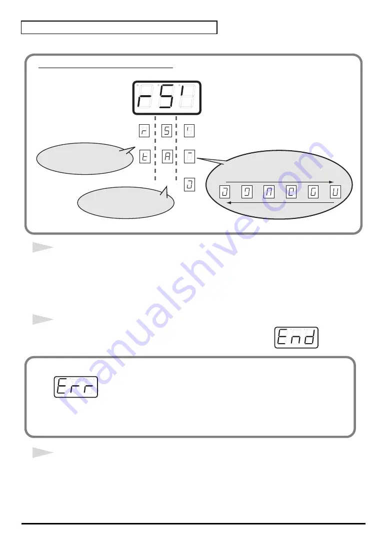
About the display in Bulk mode

fig.bulk-dis

Transmit

Receive

ALL

BULK

SINGLE

BULK

1st digit:

indicates Receive mode or 

Transmit mode

 receiving

 transmitting

Waiting to receive 
(blinking)

Waiting to transmit 
(blinking)

Transmitting 

2nd digit: 

Single Bulk or All Bulk

3rd digit: indicates 

Transmitting/Receiving/Waiting states

Error display

fig.err

If the data could not be received correctly, the display will blink “ERR”.
If this occurs, press the 

[CANCEL]

 button to cancel the “ERR” display.

Once "ERR" has been dismissed, perform the bulk reception procedure over again, from step 1.

Summary of Contents for Edirol PCR-80

Page 1: ...UELA Musicland Digital C A Av Francisco de Miranda Centro Parque de Cristal Nivel C2 Local 20 Caracas VENEZUELA TEL 212 285 8586 URUGUAY Todo Musica S A Francisco Acuna de Figueroa 1771 C P 11 800 Montevideo URUGUAY TEL 02 924 2335 DENMARK Roland Scandinavia A S Nordhavnsvej 7 Postbox 880 DK 2100 Copenhagen DENMARK TEL 3916 6200 FRANCE Roland France SA 4 Rue Paul Henri SPAAK Parc de l Esplanade F ...

Page 2: ...be done is indicated by the design contained within the circle In the case of the symbol at left it means that the power cord plug must be unplugged from the outlet The symbol alerts the user to important instructions or warnings The specific meaning of the symbol is determined by the design contained within the triangle In the case of the symbol at left it is used for general cautions warnings or...

Page 3: ...hould be located so their location or position does not interfere with their proper ventilation 102d Always grasp only the output plug or the body of the AC adaptor when plugging into or unplugging from this unit or an outlet 103b At regular intervals you should unplug the AC adaptor and clean it by usinga dry cloth to wipe all dust and other accumulations away from its prongs Also disconnect the ...

Page 4: ...01 Avoid touching or scratching the shiny underside encoded surface of the disc Damaged or dirty CD ROM discs may not be read properly Keep your discs clean using a commercially available CD cleaner Maintenance 401a For everyday cleaning wipe the unit with a soft dry cloth or one that has been slightly dampened with water To remove stubborn dirt use a cloth impreg nated with a mild non abrasive de...

Page 5: ...3 Installing Setting Up the Driver Macintosh 25 Mac OS 9 8 users 25 Installing the driver 25 Setting the driver 26 FreeMIDI settings 29 Mac OS X Users 31 Installing the driver 31 Setting the driver 32 Deutsch Installieren und Einrichten des Treibers Windows 33 Treiberinstallation 33 Windows XP Anwender 33 Windows 2000 Anwender 38 Windows Me 98 Anwender 42 Einstellungen 44 Installieren und Einricht...

Page 6: ...ows 74 Installazione del driver 74 Utenti Windows XP 74 Utenti Windows 2000 78 Utenti Windows Me 98 81 Impostazioni 83 Installazione e configurazione del driver Macintosh 85 Utenti Mac OS 9 8 85 Utenti Mac OS X 91 Español Instalación y configuración del controlador Windows 94 Instalación del controlador 94 Usuarios de Windows XP 94 Usuarios de Windows 2000 98 Usuarios de Windows Me 98 101 Configur...

Page 7: ...0 Memory mode MEMORY 121 Snapshot mode SNAPSHOT 122 Panic mode PANIC 123 Edit mode EDIT 125 Controller settings 126 NOTE ASSIGN 127 AFTERTOUCH ASSIGN 129 CONTROL CHANGE ASSIGN 132 PROGRAM CHANGE ASSIGN 135 RPN NRPN ASSIGN 138 SYS EX ASSIGN 140 TEMPO ASSIGN 146 NO ASSIGN 146 ASSIGN COPY 147 SAVE 148 OMNI 149 PROTECT 150 BULK 151 Receive mode 151 Transmit mode 153 SYSTEM 154 Setting method A 155 Set...

Page 8: ...d to the USB driver 170 Deleting the driver 173 MIDI implementation 174 Main specifications 179 INDEX 180 204 Microsoft and Windows are registered trademarks of Microsoft Corporation 206j Windows is known officially as Microsoft Windows operating system 206e Screen shots in this documents are reprinted with permission from Microsoft Corporation 207 Apple and Macintosh are registered trademark of A...

Page 9: ...r computer with the USB connector of the PCR 30 50 80 For details on connections and driver installation refer to Setup p 13 Please use only the included USB cable If you require a replacement due to loss or damage please contact a EDIROL Roland Service Center listed in the Information section at the end of this manual CD ROM This contains drivers and editors for use with the PCR 30 50 80 Template...

Page 10: ...hat are linked to your performance 4 MEMORY Button Accesses memories that are stored within the PCR 30 50 80 5 MIDI CH Button Specifies the transmission channel current channel for the keyboard and bender 6 PROGRAM CHANGE Button Transmits program change messages on the current channel 7 EDIT Button Used to assign MIDI messages to the controllers 8 DEC Button Decreases the value of a setting by one...

Page 11: ... Also in any mode except PLAY mode it functions as the ENTER button which you need to press to confirm the settings you ve made 17 OCTAVE Press OCTAVE to shift the pitch of the keyboard up or down in steps of an octave When not in PLAY mode use these buttons to return to the previous setting item the BACK button or to cancel the setting and return to PLAY mode the CANCEL button 18 BENDER Lever Thi...

Page 12: ...not operate if bus power is used In this case use the included AC adaptor 23 USB connector Use this when connecting the PCR 30 50 80 to your computer via a USB cable 24 MIDI IN OUT connectors These can be connected to the MIDI connectors of other MIDI devices to transmit and receive MIDI messages 25 Controller P1 and P2 You can connect the appropriate type of pedals to these jacks and use them as ...

Page 13: ...s p 55 Installation et configuration du pilote Macintosh p 66 Italiano Installazione e configurazione del driver Windows p 74 Installazione e configurazione del driver Macintosh p 85 Español Instalación y configuración del controlador Windows p 94 Instalación y configuración del controlador Macintosh p 105 What is a driver A driver is software that transfers data between the PCR 30 50 80 and appli...

Page 14: ... it is not set to Ignore make a note of the current setting Warn or Block Then change the setting to Ignore and click OK The installation procedure will differ depending on your system Please proceed to one of the following sections depending on the system you use Windows XP users p 14 Windows 2000 users p 18 Windows Me 98 users p 21 If you are using Windows XP Professional you must log on using a...

Page 15: ... drive name of your CD ROM drive 10The SetupInf dialog box will appear You are now ready to install the driver 11Use the USB cable to connect the PCR 30 50 80 to your computer 1 With the power switch turned OFF connect the AC adaptor to the PCR 30 50 80 2 Connect the AC adaptor to an electrical outlet 3 Use the USB cable to connect the PCR 30 50 80 to your computer 12Set the PCR 30 50 80 s power s...

Page 16: ...g box will appear Input the following into the Copy files from field and click OK D Driver USB_XP2K The drive name D may be different for your system Specify the drive name of your CD ROM drive If the What action do you want Windows to take setting was not set to Ignore a Hardware Installation dialog box will appear If What action do you want Windows to take is set to Warn 1 Click Continue Anyway ...

Page 17: ...dows using the user name of an administrative account e g Administrator 2 Click the Windows start menu and from the menu select Control Panel 3 In Pick a category click Performance and Maintenance 4 In or pick a Control Panel icon click the System icon The System Properties dialog box will appear Depending on how your system is set up the System icon may be displayed directly in the Control Panel ...

Page 18: ...iver Signing Open the Driver Signing Options dialog box 5 Make sure that File signature verification is set to Ignore If it is set to Ignore simply click OK If it is not set to Ignore make a note of the current setting Warn or Block Then change the setting to Ignore and click OK 6 Close the System Properties dialog box Click OK 7 Exit all currently running software applications Also close any open...

Page 19: ...nnect the PCR 30 50 80 to your computer 13Set the PCR 30 50 80 s power switch to the ON position Once the connections have been completed turn on power to your various devices in the order specified By turning on devices in the wrong order you risk causing malfunction and or damage to speakers and other devices This unit is equipped with a protection circuit A brief interval a few seconds after po...

Page 20: ...alog box does not appear p 171 If you changed File signature verification If you changed the File signature verification setting restore the original setting after Windows restarts 1 After Windows restarts log in to Windows as a user with administrative privileges such as Administrator 2 In the Windows desktop right click the My Computer icon and from the menu that appears select Properties The Sy...

Page 21: ...ver USB_ME98 SETUPINF EXE The drive name D may be different for your system Specify the drive name of your CD ROM drive 6 The SetupInf dialog box will appear You are now ready to install the driver 7 Use the USB cable to connect the PCR 30 50 80 to your computer 1 With the power switch turned OFF connect the AC adaptor to the PCR 30 50 80 2 Connect the AC adaptor to an electrical outlet 3 Use the ...

Page 22: ...indows 9 The driver will be installed automatically 10In the dialog box click OK If a message recommends that you restart Windows restart Windows as directed Next you need to make the driver settings MIDI input and output destinations p 23 ...

Page 23: ...d Multimedia icon to open the Sounds and Multimedia Properties dialog box 3 Click the Audio tab fig 2 28_30 4 For MIDI music playback click the located at the right of Default device or in Windows 2000 Me Preferred device and select the MIDI device from the list that appears If you want to use Media Player to play a sound module connected to the PCR s MIDI OUT connector select EDIROL PCR MIDI OUT ...

Page 24: ... If you want to use Media Player to play a sound module connected to the PCR s MIDI OUT connector select EDIROL PCR MIDI OUT 5 Close the Multimedia Properties dialog box Click OK to complete the settings 6 Make MIDI device settings on your sequencer software For details on the MIDI OUT IN device to select refer to About the ports when using a USB connection p 159 For details on MIDI device setting...

Page 25: ...nstallation procedure will differ depending on your system Please proceed to one of the following sections depending on the system you use Mac OS 9 8 users p 25 Mac OS X users p 31 OMS can be found in the OMS 2 3 8 E folder within the OMS folder of the CD ROM If you would like to know more about OMS refer to OMS_2 0E_Mac pdf which can be found in the same folder If a PCR 30 50 80 is already connec...

Page 26: ...connect the AC adaptor to the PCR 30 50 80 2 Connect the AC adaptor to an electrical outlet 3 Use the USB cable to connect the PCR 30 50 80 to your computer 2 Set the PCR 30 50 80 s power switch to the ON position fig 3 3 3 From the CD ROM drag the Driver E Mac OS 9 8 OMS Setting folder to the hard disk of your Macintosh to copy it fig 3 4 4 In the Opcode OMS Application folder where you installed...

Page 27: ... appear Click Cancel If you accidentally clicked OK click Cancel in the next screen fig 3 8_35 7 Choose Open from the File menu From the Setting folder that you copied in step 3 select the PCR file and click Open A screen like the one shown here will appear fig 3 9_35 8 From the Edit menu select OMS MIDI Setup In the OMS MIDI Setup dialog box that appears check Run MIDI in background and click OK ...

Page 28: ... connector icon shown in the diagram at the right If you hear sound the settings have been made correctly 12Exit OMS Setup From the File menu choose Exit If the AppleTalk confirmation dialog box appears click OK to close the dialog box 13Make MIDI device settings on your sequencer software For details on the MIDI OUT IN device to select refer to About the ports when using a USB connection p 159 A ...

Page 29: ...ear Click Continue 2 When the FreeMIDI Preferences dialog box appear Click Cancel 3 The About Quick Setup dialog box will appear Click Cancel 6 From the File menu choose Open 7 Select PCR from the FreeMIDI Setting folder you copied in step 3 and click Open 8 Verify that MIDI transmission and reception occur correctly From the MIDI menu choose Check Connections This unit is equipped with a protecti...

Page 30: ...ns to end the test 11From the File menu choose Quit to exit FreeMIDI Setup 12Make MIDI device settings on your sequencer software For details on the MIDI OUT IN device to select refer to About the ports when using a USB connection p 159 For details on port refer to About the ports when using a USB connection p 159 For details on connecting a MIDI sound module refer to the owner s manual for your M...

Page 31: ... password and click OK 5 The display will indicate Welcome to EDIROL PCR USB Driver installation Click Continue 6 The display will indicate Important message Read the contents and click Continue 7 The display will indicate Select the location for installation Click the drive in which the operating system is installed to select it and then click Continue 8 The display will indicate Easy installatio...

Page 32: ...r sequencer software please note the following points Connect the PCR 30 50 80 to your computer via a USB cable before you start up your sequencer or other software Do not disconnect the USB cable from the PCR 30 50 80 while your sequencer or other software is running Disconnect the USB cable from the PCR 30 50 80 only after you have quit your sequencer or other software Leave the Sleep function o...

Page 33: ...Systemsteuerungssymbol auf das Symbol System Die Vorgehensweise bei der Installation hängt von Ihrem System ab Bitte lesen Sie abhängig von dem von Ihnen verwendeten System in einem der folgenden Abschnitte weiter Windows XP Anwender S 33 Windows 2000 Anwender S 38 Windows Me 98 Anwender S 42 Wenn Sie Windows XP Professional verwenden müssen Sie sich mit einem Benutzernamen vom Typ Administrations...

Page 34: ...Anwendungen Schließen Sie außerdem alle noch geöffneten Programmfenster Wenn Sie ein Virenschutzprogramm oder ähnliche Software verwenden müssen Sie diese ebenfalls beenden 7 Halten Sie die CD ROM bereit Legen Sie die CD ROM in das CD ROM Laufwerk Ihres Computers ein 8 Klicken Sie auf die Windows Schaltfläche Start Wählen Sie im daraufhin angezeigten Menü die Option Ausführen Öffnen Sie das Dialog...

Page 35: ...er Assistent für das Suchen neuer Hardware erscheint Prüfen Sie ob der Bildschirm EDIROL PCR anzeigt wählen Sie Software von einer Liste oder bestimmten Quelle installieren für fortgeschrittene Benutzer und klicken Sie auf Weiter fig 2 7 14Im Bildschirm wird folgende Meldung angezeigt Wählen Sie die Such und Installationsoptionen Wählen Sie Nicht suchen sondern den zu installierenden Treiber selbs...

Page 36: ...Neue Hardware gefunden in der Nähe der Task Leiste angezeigt wird 19Nachdem der Treiber installiert wurde wird das Dialogfeld Geänderte Systemeinstellungen angezeigt Klicken Sie auf Ja Windows startet anschließend automatisch neu Wenn die Einstellung für Wie soll Windows vorgehen nicht Ignorieren lautet wird das Dialogfeld Hardware Installation angezeigt Wenn für Wie soll Windows vorgehen Warnen a...

Page 37: ...und Wartung 4 Klicken Sie in oder wählen Sie ein Systemsteuerungssymbol auf das Symbol System Daraufhin werden die Systemeigenschaften angezeigt Abhängig von der Konfiguration Ihres Systems kann es vorkommen dass das Symbol System nicht sofort in der Systemsteuerung in der klassischen Anzeige angezeigt wird Doppelklicken Sie in diesem Fall auf das Symbol System 5 Klicken Sie auf die Registerkarte ...

Page 38: ... Öffnen Sie das Dialogfeld Treibersignaturoptionen 5 Stellen Sie sicher dass für Dateisignaturverifizierung Ignorieren aktiviert ist Wenn Ignorieren eingestellt ist klicken Sie einfach auf OK Wenn Ignorieren nicht eingestellt ist notieren Sie sich die aktuelle Einstellung Warnen oder Sperren Anschließend ändern Sie die Einstellung auf Ignorieren und klicken auf OK 6 Schließen Sie das Dialogfeld Sy...

Page 39: ...installiert werden 12Verwenden Sie das USB Kabel um das PCR 30 50 80 mit Ihrem Computer zu verbinden 1 Verbinden Sie bei ausgeschaltetem Netzschalter den Wechselstromadapter mit dem PCR 30 50 80 2 Verbinden Sie den Wechselstromadapter mit einer elektrischen Steckdose 3 Verwenden Sie das USB Kabel um das PCR 30 50 80 mit Ihrem Computer zu verbinden 13Bringen Sie den Netzschalter des PCR 30 50 80 in...

Page 40: ...das Dialogfeld Geänderte Systemeinstellungen angezeigt Klicken Sie auf Ja Windows startet anschließend automatisch neu Wenn in für Dateisignaturverifizierung nicht Ignorieren aktiviert wurde erscheint die Meldung Digitalsignatur nicht gefunden Wenn für Dateisignaturverifizierung Warnen aktiviert ist 1 Klicken Sie auf Ja 2 Setzen Sie die Installation fort Wenn für Dateisignaturverifizierung Sperren...

Page 41: ...indows Desktop mit der rechten Maustaste auf das Symbol Arbeitsplatz und wählen Sie im daraufhin angezeigten Menü Eigenschaften Daraufhin wird das Dialogfeld Systemeigenschaften angezeigt 3 Klicken Sie auf die Registerkarte Hardware und klicken Sie anschließend auf Treibersignierung Daraufhin werden die Treibersignaturoptionen angezeigt 4 Stellen Sie die ursprünglichen Einstellungen für Dateisigna...

Page 42: ...en Sie diese ebenfalls beenden 3 Halten Sie die CD ROM bereit Legen Sie die CD ROM in das CD ROM Laufwerk Ihres Computers ein 4 Klicken Sie auf die Windows Schaltfläche Start Wählen Sie im daraufhin angezeigten Menü die Option Ausführen Öffnen Sie das Dialogfeld Ausführen fig 2 19a_30 5 Geben Sie im angezeigten Dialogfeld Folgendes in das Feld Öffnen ein und klicken Sie auf OK D Driver USB_ME98 SE...

Page 43: ...d automatisch installiert werden 10Klicken Sie im Dialogfeld auf OK Wenn Sie eine Meldung erhalten die Ihnen empfiehlt Windows neu zu starten starten Sie Windows neu Dieses Gerät ist mit einem Schutzschaltkreis ausgestattet Nach dem Einschalten benötigt das Gerät eine kurze Zeitspanne einige Sekunden bis es den normalen Betrieb aufnimmt Nachdem die Anschlüsse fertig gestellt wurden schalten Sie di...

Page 44: ...r Sounds und Multimedia zu öffnen 3 Klicken Sie auf die Registerkarte Audio fig 2 28_30 4 Klicken Sie bei MIDI Musikwiedergabe auf das das sich rechts von Standardgerät befindet bzw in Windows 2000 Me rechts von Bevorzugtes Gerät und wählen Sie das MIDI Gerät aus der angezeigten Liste aus Wenn Sie den Media Player verwenden möchten um ein Soundmodul abzuspielen das mit dem MIDI OUT Stecker des PCR...

Page 45: ...ezeigten Liste Wenn Sie den Media Player verwenden möchten um ein Soundmodul abzuspielen das mit dem MIDI OUT Stecker des PCRs verbunden ist wählen Sie EDIROL PCR MIDI OUT 4 Schließen Sie das Dialogfeld Eigenschaften für Multimedia Klicken Sie auf OK um die Konfiguration abzuschließen 5 Nehmen Sie die MIDI Geräteeinstellungen auf Ihrer Sequenzer Software vor Wenn Sie weitere Informationen zu dem M...

Page 46: ...3 8 E der sich im Ordner OMS der CD ROM befindet Wenn Sie mehr über OMS erfahren möchten lesen Sie bitte die Datei OMS_2 3_Mac pdf Online Handbuch im Ordner OMS2 3 8E der sich im Ordner OMS der CD ROM befindet Trennen Sie das PCR 30 50 80 vom Macintosh bevor Sie die Installation ausführen Wenn das PCR 30 50 80 eingeschaltet wird wird eine Meldung ähnlich der folgenden Meldung angezeigt wenn der Ma...

Page 47: ...3 Doppelklicken Sie auf das Symbol PCR Driver E Installer das sich im Ordner Driver E Mac OS 9 8 OMS auf der CD ROM befindet um das Installationsprogramm zu starten 4 Prüfen Sie den Installationsort und klicken Sie auf Install fig 3 2_40 5 Falls eine Meldung wie abgebildet angezeigt wird klicken Sie auf Continue Alle anderen aktuell ausgeführten Anwendungen werden anschließend beendet und die Inst...

Page 48: ...pelklicken Sie im Ordner Opcode OMS Application in dem Sie OMS installiert haben auf OMS Setup um die Installation zu starten fig 3 5_35 5 Wenn ein Dialogfeld ähnlich dem abgebildeten Dialogfeld angezeigt wird klicken Sie auf Turn It Off Anschließend wird ein Dialogfeld für die Bestätigung angezeigt Klicken Sie hier auf OK Nachdem die Anschlüsse fertig gestellt wurden schalten Sie die verschie den...

Page 49: ...eld ähnlich dem hier gezeigten Dialogfeld wird angezeigt fig 3 9_35 8 Wählen Sie im Menü Edit die Option OMS MIDI Setup Aktivieren Sie im daraufhin angezeigten Dialogfeld OMS MIDI Setup die Option Run MIDI in background und klicken Sie auf OK fig 3 10 9 Wählen Sie im Menü File die Option Make Current Wenn Sie die Option Make Current nicht auswählen können wurde sie bereits angewendet und Sie könne...

Page 50: ...undmoduls über den MIDI OUT des PCR 30 50 80 sollte bei Klicken des Midi Symbols ein Ton erklingen 12Beenden Sie OMS Setup Wählen Sie im Menü File die Option Exit Klicken Sie im Dialogfeld AppleTalk Confirmation auf OK um das Dialogfeld zu schließen Weitere Informationen zum Anschluss eines MIDI Soundmoduls erhalten Sie im Benutzerhandbuch für Ihr MIDI Soundmodul Damit wurden die Schritte ausgefüh...

Page 51: ...enn die Software zum ersten Mal ausgeführt wird wird das Dialogfeld Welcome to FreeMIDI angezeigt Klicken Sie auf Continue 7 Wenn das Dialogfeld FreeMIDI Preferences angezeigt wird klicken Sie auf Cancel 8 Wenn das Dialogfeld About Quick Setup angezeigt wird klicken Sie auf Cancel 9 Wählen Sie im Menü File die Option Open 10Wählen Sie im Ordner FreeMIDI Setting den Sie in Schritt 3 kopiert haben d...

Page 52: ...rten Sie den Macintosh neu 2 Halten Sie die CD ROM bereit Legen Sie die CD ROM in das CD ROM Laufwerk Ihres Computers ein 3 Doppelklicken Sie im Ordner Driver Mac OS X auf der CD ROM auf PCRUSBDriver pkg Klicken Sie unter Mac OS X v10 1 5 auf das Schlüsselsymbol für die Authentifizierung 4 Geben Sie in das Dialogfeld Authentication Ihr Kennwort ein und klicken Sie auf OK Weitere Informationen zum ...

Page 53: ... Nach Installation ist ein Neustart erforderlich Klicken Sie anschließend auf Continue installation 10In der Anzeige erscheint Folgendes The software was successfully installed Das Programm wurde erfolgreich installiert Klicken Sie auf Restart um Ihren Computer neu zu starten Vorsichtsmaßnahmen bei der Verwendung des PCR Bevor Sie Ihr Sequenzerprogramm verwenden beachten Sie bitte Folgendes Verwen...

Page 54: ...omputer zu verbinden 2 Bringen Sie den Netzschalter des PCR 30 50 80 in die Position ON 3 Nehmen Sie in Ihrem Sequenzerprogramm die Einstellungen für MIDI Geräte vor Nähere Informationen dazu welches MIDI OUT IN Gerät ausgewählt werden sollte erhalten Sie unter About the ports when using a USB connection S 159 Detaillierte Informa tionen zu den MIDI Geräteeinstellungen erhalten Sie im Handbuch zu ...

Page 55: ...re Que voulez vous faire est défini sur Ignorer Si ce paramètre est réglé sur Ignorer cliquez sur OK Si elle n est pas définie sur Ignorer notez le paramètre indiqué Avertir ou Bloquer Choisissez ensuite Ignorer et cliquez sur OK La procédure d installation dépend de votre système d exploitation Veuillez lire la section qui vous concerne Windows XP p 55 Windows 2000 p 59 Windows Me 98 p 62 Si vous...

Page 56: ... lecteur de CD de votre ordinateur par exemple E ou F 10La boîte de dialogue SetupInf s affiche Vous êtes maintenant prêt à installer le pilote 11Utilisez le câble USB pour brancher le PCR 30 50 80 à votre ordinateur 1 L interrupteur d alimentation sur OFF branchez le cordon secteur sur le PCR 30 50 80 2 Branchez le cordon secteur sur une prise électrique secteur 3 Utilisez le câble USB pour branc...

Page 57: ... sur OK 17La boîte de dialogue Fichiers nécessaires s affiche Tapez ce qui suit dans le champ Copier les fichiers depuis puis cliquez sur OK D Driver USB_XP2K La lettre du lecteur D n est pas forcément celle de votre ordinateur Tapez la lettre affectée au lecteur de CD de votre ordinateur par exemple E ou F Si le paramètre Que voulez vous faire n est pas défini sur Ignorer la boîte de dialogue Ins...

Page 58: ... d administrateur 2 Cliquez sur le menu Démarrer de Windows puis dans le menu qui s affiche choisissez Panneau de configuration 3 Dans Choisissez une catégorie cliquez sur Performances et maintenance 4 Dans ou choisissez une icône du Panneau de configuration cliquez sur l icône Système La boîte de dialogue Propriétés système s affiche Selon la configuration de votre ordinateur l icône Système s af...

Page 59: ...nglet Matériel puis cliquez sur Signature du pilote Ouvrez la boîte de dialogue Options de signature du pilote 5 Assurez vous que l option Vérification des signatures de fichiers est définie sur Ignorer Si ce paramètre est réglé sur Ignorer cliquez sur OK S il n est pas défini sur Ignorer notez le paramètre indiqué Avertir ou Bloquer Choisissez ensuite Ignorer et cliquez sur OK 6 Fermez la boîte d...

Page 60: ... USB pour brancher le PCR 30 50 80 à votre ordinateur 13Placez l interrupteur d alimentation du PCR 30 50 80 sur ON Une fois les connexions effectuées mettez sous tension les différents appareils dans l ordre spécifié Ne pas respecter cet ordre peut entraîner des dysfonctionnements et ou endommager les enceintes ou tout autre appareil Cet appareil est équipé d un circuit de protection Après la mis...

Page 61: ...Disk dialog box does not appear p 171 Si vous avez modifié l option Vérification de la signature des fichiers Si vous avez modifié Vérification des signatures des fichiers restaurez le paramètre original après le redémarrage de Windows 1 Une fois Windows redémarré ouvrez une session Windows avec des privilèges d administration par exemple en ouvrant une session Administrateur 2 Sur le bureau Windo...

Page 62: ...CD ROM Introduisez le dans le lecteur de CD de votre ordinateur 4 Cliquez sur le bouton Démarrer de Windows Dans le menu qui s affiche sélectionnez Exécuter Ouvrez la boîte de dialogue Exécuter voir ci dessous fig 2 19a_30 5 Dans la boîte de dialogue qui s affiche tapez ce qui suit dans le champ Ouvrir puis cliquez sur OK D Driver USB_ME98 SETUPINF EXE La lettre du lecteur D n est pas forcément ce...

Page 63: ...tion du PCR 30 50 80 sur ON 9 Le pilote s installe automatiquement 10Dans la boîte de dialogue cliquez sur OK Si un message vous recommande de relancer Windows faites le Cet appareil est équipé d un circuit de protection Après la mise sous tension attendez quelques secondes avant d utiliser l appareil Une fois les connexions effectuées mettez sous tension les différents appareils dans l ordre spéc...

Page 64: ... Multimédia pour ouvrir la boîte de dialogue Propriétés de Sons et multimédia 3 Cliquez sur l onglet Audio fig 2 28_30 4 Pour Lecture MIDI cliquez sur le situé à droite de Périphérique par défaut avec Windows 2000 Me Périphérique par défaut puis sélectionnez un périphérique MIDI dans la liste qui s affiche Si vous voulez utiliser Media Player pour piloter un module de sons branché au connecteur MI...

Page 65: ...onnez le périphérique MIDI dans la liste qui s affiche Si vous voulez utiliser Media Player pour piloter un module de sons branché au connecteur MIDI OUT du PCR sélectionnez EDIROL PCR MIDI OUT 5 Fermez la boîte de dialogue Propriétés de Multimédia Cliquez sur OK pour terminer les réglages 6 Procédez aux réglages MIDI du périphérique dans votre application séquenceur Pour plus de détails sur le pé...

Page 66: ...MS se trouve dans le dossier OMS 2 3 8 E du dossier OMS sur le CD ROM Pour plus d information sur OMS veuillez lire le document OMS_2 3_Mac pdf manuel au format Acrobat situé dans le dossier OMS Driver du dossier OMS sur le CD ROM Débranchez l PCR 30 50 80 du Macintosh avant d effectuer l installation Si le PCR 30 50 80 est allumé un message similaire à celui présenté ici s affiche à la mise sous ...

Page 67: ...tres Paramètres OMS 1 Utilisez le câble USB pour relier le PCR 30 50 80 à votre ordinateur 1 L interrupteur d alimentation sur OFF branchez le cordon secteur sur le PCR 30 50 80 2 Branchez le cordon secteur sur une prise électrique secteur 3 Utilisez le câble USB pour relier le PCR 30 50 80 à votre ordinateur 2 Placez l interrupteur d alimentation du PCR 30 50 80 sur ON fig 3 3 fig 3 3 3 Depuis le...

Page 68: ... Cliquez sur Annuler Si vous avez cliqué sur OK par erreur cliquez sur Annuler dans la boîte suivante fig 3 7 fig 3 8_35 7 Choisissez Open dans le menu File Dans le dossier Setting que vous avez copié à l étape 3 sélectionnez le fichier PCR puis cliquez sur Open Un écran similaire à celui présenté ici s affiche fig 3 9_35 8 Dans le menu Edit sélectionnez OMS MIDI Setup Dans la boîte de dialogue OM...

Page 69: ...églages sont corrects Lorsque vous déplacez le curseur de la souris sur l icône représentant une prise MIDI le curseur se transforme en note de musique Si un module de sons est branché en sortie MIDI OUT du PCR 30 50 80 cliquer sur l icône de prise MIDI du schéma de droite produira un son les réglages sont alors corrects 12Quittez OMS Setup Dans le menu File choisissez Exit Si la boîte de dialogue...

Page 70: ...omputer cliquez sur FreeMIDI 6 Au premier lancement de FreeMIDI une boîte de dialogue Welcome to FreeMIDI s affiche Cliquez sur Continue 7 Quand la boîte de dialogue FreeMIDI Preferences s affiche cliquez sur Cancel 8 Quand la boîte de dialogue About Quick Setup s affiche cliquez sur Cancel 9 Dans le menu File sélectionnez Open 10Sélectionnez PCR dans le dossier FreeMIDI Settings que vous avez cop...

Page 71: ...ez tous les câbles USB à l exception de ceux de votre clavier et de votre souris et redémarrez votre Macintosh 2 Munissez vous du CD ROM Introduisez le dans le lecteur de CD de votre ordinateur 3 Dans le dossier Driver Mac OS X du CD ROM cliquez deux fois sur PCRUSBDriver pkg Dans Mac OS X v10 1 5 cliquez sur le symbole du verrou pour vous identifier 4 Dans la boîte de dialogue d identification en...

Page 72: ...rdinateur une fois l installation terminée Cliquez sur Continue installation 10 The software was successfully installed s affiche Le logiciel a été installé avec succès Cliquez sur Restart pour redémarrer votre ordinateur Précautions à prendre lors de l utilisation de PCR Avant d utiliser votre logiciel séquenceur tenez compte des points suivants Branchez le PCR 30 50 80 à votre ordinateur avec un...

Page 73: ... câble USB pour brancher le PCR 30 50 80 à votre ordinateur 2 Placez l interrupteur d alimentation du PCR 30 50 80 sur ON 3 Procédez aux réglages MIDI du périphérique dans votre séquenceur logiciel Pour plus de détails sur le périphérique MIDI OUT IN à sélectionner reportez vous à la section About the ports when using a USB connection p 159 Pour plus de détails sur les réglages MIDI reportez vous ...

Page 74: ...n è impostata su Ignora prendere nota dell impostazione corrente di avviso o di blocco Modificare quindi l impostazione su Ignora e fare clic su OK La procedura d installazione dipenderà dal sistema utilizzato Passare ad una delle sezioni seguenti a seconda del sistema utilizzato Utenti Windows XP pag 74 Utenti Windows 2000 pag 78 Utenti Windows Me 98 pag 81 Se si utilizza Windows XP Professional ...

Page 75: ...are il nome dell unità CD ROM utilizzata 10Appare la finestra di dialogo SetupInf È ora possibile installare il driver 11Utilizzare il cavo USB per collegare il PCR 30 50 80 al computer 1 Dopo aver spostato l interruttore di alimentazione su OFF collegare l adattatore AC al PCR 30 50 80 2 Collegare l adattatore AC a una presa elettrica 3 Utilizzare il cavo USB per collegare il PCR 30 50 80 al comp...

Page 76: ...17Viene visualizzata la finestra di dialogo Richiesta file Immettere quanto segue nel campo Copia file da e fare clic su OK D Driver USB_XP2K L identificativo dell unità D potrebbe essere diverso da quello del sistema utilizzato In questo caso specificare il nome dell unità CD ROM utilizzata Se l impostazione Scegliere una delle seguenti opzioni non è stata impostata su Ignora comparirà il messagg...

Page 77: ... nome utente dotato di privilegi di tipo amministrativo ad esempio Administrator 2 In Windows fare clic sul menu Start e nel menu selezionare Pannello di controllo 3 In Scegliere una categoria fare clic su Prestazioni e manutenzione 4 In o un icona del Pannello di controllo fare clic sull icona Sistema Viene visualizzata la finestra di dialogo Proprietà del sistema A seconda di come il sistema è c...

Page 78: ...ante Firma driver Aprire la finestra di dialogo Opzioni firma driver 5 Accertarsi che Verifica firma file sia impostato su Ignora Se è attivata l opzione Ignora fare clic su OK Se non è impostata su Ignora prendere nota dell impostazione corrente di avviso o di blocco Modificare quindi l impostazione su Ignora e fare clic su OK 6 Chiudere la finestra di dialogo Proprietà del sistema Fare clic su O...

Page 79: ... cavo USB per collegare il PCR 30 50 80 al computer 13Spostare l interruttore di alimentazione del PCR 30 50 80 in posizione ON Una volta terminati i collegamenti accendere i vari dispositivi nell ordine indicato Se i dispositivi vengono accesi nell ordine sbagliato si rischia di provocare malfunziona menti e o danni ai diffusori e agli altri dispositivi Questo apparecchio è provvisto di un circui...

Page 80: ...la sezione The Insert Disk dialog box does not appear pag 171 Se è stata modificata l impostazione Verifica firma file Se l impostazione Verifica firma file è stata cambiata ripristinare l impostazione d origine dopo aver riavviato Windows 1 Dopo aver riavviato Windows collegarsi a Windows come un utente dotato di privilegi di amministrazione ad esempio come Administrator 2 Sul desktop di Windows ...

Page 81: ...le accertarsi che sia anch esso chiuso 3 Preparare il CD ROM Inserire il CD nell unità CD ROM del computer 4 Fare clic sul pulsante Start di Windows Nel menu visualizzato selezionare Esegui Aprire la finestra di dialogo Esegui fig 2 19a_30 5 Nella finestra di dialogo che appare immettere quanto segue nel campo Apri e fare clic su OK D Driver USB_ME98 SETUPINF EXE L identificativo dell unità D potr...

Page 82: ...nstallato automaticamente 10Nella finestra di dialogo fare clic su OK Se appare un messaggio che invita a riavviare Windows riavviarlo come consigliato Questo apparecchio è provvisto di un circuito di protezione È necessario aspettare qualche secondo dopo l accensione prima che l apparecchio funzioni normalmente Una volta terminati i collegamenti accendere i vari dispositivi nell ordine indicato S...

Page 83: ...ra Proprietà suoni e multimedia 3 Fare clic sulla scheda Audio fig 2 28_30 4 Per Riproduzione musica MIDI fare clic su a destra di Periferica predefinita oppure in Windows 2000 Me Periferica preferenziale e selezionare la periferica MIDI nell elenco visualizzato Per utilizzare Windows Media Player per riprodurre un modulo sonoro collegato al connettore MIDI OUT del PCR selezionare EDIROL PCR MIDI ...

Page 84: ...collegato al connettore MIDI OUT del PCR selezionare EDIROL PCR MIDI OUT 5 Chiudere la finestra di dialogo Proprietà multimediali Fare clic su OK per completare le impostazioni 6 Configurare la periferica MIDI sul sofware sequencer Per maggiori informazioni sulla periferica MIDI OUT IN da selezionare fare riferimento alla sezione About the ports when using a USB connection pag 159 Per maggiori inf...

Page 85: ...trova nella cartella OMS 2 3 8 E all interno della cartella OMS del CD ROM Per avere maggiori informazioni sul software OMS consultare il file OMS_2 3_Mac pdf manuale in linea che si trova nella cartella OMS 2 3 8E all interno della cartella OMS sul CD ROM Scollegare l PCR 30 50 80 dal Macintosh prima di eseguire l installazione Se l PCR 30 50 80 è acceso comparirà un messaggio come quello sotto i...

Page 86: ...ue Le applicazioni in corso di esecuzione verranno chiuse e l installazione proseguirà 6 Verrà visualizzata una finestra di dialogo indicante Installation completed Fare clic su Restart per riavviare il Macintosh Impostazioni Impostazioni OMS 1 Utilizzare il cavo USB per collegare l PCR 30 50 80 al computer 1 Dopo aver spostato l interruttore di alimentazione su OFF collegare il adattatore AC all ...

Page 87: ...zata una finestra di dialogo di conferma fare clic su OK fig 3 6_35 6 Verrà visualizzata la finestra di dialogo Create a New Studio Setup Fare clic su Cancel Se è stato selezionato accidentalmente il pulsante OK fare clic su Cancel nella finestra successiva fig 3 8_35 7 Selezionare Open nel menu File Nella cartella Settings copiata al passo 3 selezionare il file PCR e fare clic su Open Verrà visua...

Page 88: ...e la tastiera PCR 30 50 80 Se la freccia sotto al numero 2 o al numero 3 lampeggia vedi diagramma a destra le impostazioni sono state eseguite correttamente Spostando il cursore del mouse vicino all icona del connettore MIDI il puntatore cambierà forma in quella di una nota musicale Se un modulo sonoro MIDI è collegato alla presa MIDI OUT della tastiera PCR 30 50 80 fai click sull icona del connet...

Page 89: ...IDI e fare doppio clic sull icona FreeMIDI Setup per avviare l applicazione 5 Quando appare il messaggio OMS is installed on this computer fare clic su FreeMIDI 6 Al primo avvio di FreeMIDI comparirà la finestra di dialogo Welcome to FreeMIDI Fare clic su Continue 7 Nella finestra di dialogo FreeMIDI Preferences fare clic su Cancel 8 Nella finestra di dialogo About Quick Setup fare clic su Cancel ...

Page 90: ...nnettore MIDI che appare nel diagramma a destra Se viene generato un suono le impostazioni sono state eseguite correttamente 13Scegliere di nuovo il comando Check Connections nel menu MIDI per concludere il test 14Nel menu File scegliere Quit per uscire da FreeMIDI Setup Si consiglia di disattivare AppleTalPer maggiori informazioni sul collega mento del modulo sonoro MIDI fare riferimento al manua...

Page 91: ...à il seguente messaggio Welcome to the EDIROL PCR USB Driver installation Fare clic su Continue 6 Verrà visualizzato il seguente messaggio Important message Controllare il contenuto della finestra e fare clic su Continue 7 Sullo schermo comparirà il messaggio Select the location for installation Selezionare l unità dove è installato il sistema e fare clic su Continue 8 Verrà visualizzato il seguen...

Page 92: ...tware sequencer o altri programmi Non scollegare il cavo USB dalla tastiera PCR 30 50 80 mentre è in esecuzione il software sequencer o un altro programma Scollegare il cavo USB dalla tastiera PCR 30 50 80 solo dopo aver chiuso il sequencer o qualsiasi altro programma utilizzato Non attivare la funzione Sleep del Macintosh La tastiera PCR 30 50 80 non funziona nella configurazione Classic di Mac O...

Page 93: ...la tastiera PCR 30 50 80 al computer 2 Spostare l interruttore di alimentazione della tastiera PCR 30 50 80 in posizione ON 3 Configurare la periferica MIDI sul sofware sequencer Per maggiori informazioni sulla periferica MIDI OUT IN da selezionare fare riferimento alla sezione About the ports when using a USB connection pag 159 Per maggiori informazioni sulle impostazioni della periferica MIDI fa...

Page 94: ...ceptar Si no está en Omitir anótese la configuración actual Avisar o Bloquear A continuación cambie la configuración a Omitir y haga clic en Aceptar El procedimiento de instalación variará en función del sistema Pase a uno de los siguientes apartados en función del sistema que utilice Usuarios de Windows XP pág 94 Usuarios de Windows 2000 pág 98 Usuarios de Windows Me 98 pág 101 Si es usuario de W...

Page 95: ...ad de CD ROM 10Aparecerá el cuadro de diálogo SetupInf Ahora puede instalar el controlador 11Utilice el cable USB para conectar la unidad PCR 30 50 80 al PC 1 Con el interruptor de alimentación apagado OFF conecte el adaptador de CA a la unidad PCR 30 50 80 2 Conecte el adaptador de CA a una toma de corriente eléctrica 3 Utilice el cable USB para conectar la unidad PCR 30 50 80 al PC 12Coloque el ...

Page 96: ...pecifique lo siguiente en el campo Copiar archivos de y haga clic en Aceptar D Driver USB_XP2K El nombre de la unidad D puede ser diferente para su sistema Especifique el nombre de la unidad de CD ROM Si el valor de Qué acción desea que realice Windows no se ha establecido en Omitir aparecerá el cuadro de diálogo Instalación de hardware Si la opción Qué acción desea que realice Windows está establ...

Page 97: ...e usuario con algún tipo de cuenta de administración Administrador por ejemplo 2 Haga clic en el menú Inicio de Windows y seleccione Panel de control 3 En Elija una categoría haga clic en Rendimiento y mantenimiento 4 En o elija un icono del Panel de control haga clic en el icono Sistema Aparecerá el cuadro de diálogo Propiedades del sistema En función de cómo tenga configurado el sistema puede qu...

Page 98: ...a el cuadro de diálogo Opciones de firma del controlador 5 Asegúrese de establecer Verificación de la firma de archivo en Omitir Si ya está establecido en Omitir haga clic en Aceptar Si no está establecido en Omitir anote el valor actual Avisar o Bloquear A continuación cambie la configuración a Omitir y haga clic en Aceptar 6 Cierre el cuadro de diálogo Propiedades del sistema Haga clic en Acepta...

Page 99: ...entación de la unidad PCR 30 50 80 en la posición ON encendido Una vez completadas las conexiones encienda los diferentes aparatos en el orden especificado Si enciende los aparatos en un orden incorrecto podrían producirse anomalías en el funciona miento o daños en los altavoces y otros aparatos Esta unidad viene equipada con un circuito de protección Es necesario dejar pasar un pequeño intervalo ...

Page 100: ...Si ha cambiado Verificación de la firma del archivo Si ha modificado el valor de Verificación de la firma del archivo restaure el valor original después de que se reinicie Windows 1 Una vez se haya reiniciado Windows inicie la sesión de Windows como un usuario con privilegios de administración como por ejemplo Administrador 2 En el escritorio de Windows haga clic con el botón secundario del ratón ...

Page 101: ...a un programa antivirus o software similar también deberá cerrarlo 3 Prepare el CD ROM Inserte el CD ROM en la unidad de CD ROM del PC 4 Haga clic en el botón Inicio de Windows En el menú que aparecerá seleccione Ejecutar Abra el cuadro de diálogo Ejecutar fig 2 19a_30 5 En el cuadro de diálogo que aparecerá escriba lo siguiente en el campo Abrir y haga clic en Aceptar D Driver USB_ME98 SETUPINF E...

Page 102: ...automáticamente 10En el cuadro de diálogo haga clic en Aceptar Si aparece un mensaje que le recomienda que reinicie Windows reinicie el sistema operativo como se le indica Esta unidad viene equipada con un circuito de protección Es necesario dejar pasar un pequeño intervalo unos segundos después de encender la unidad para que ésta funcione correctamente Una vez completadas las conexiones encienda ...

Page 103: ...cuadro de diálogo Propiedades de sonidos y multimedia 3 Haga clic en la ficha Audio fig 2 28_30 4 Para la reproducción de música MIDI haga clic en que aparece a la derecha de Dispositivo predeterminado o Dispositivo preferido en Windows 2000 Me y seleccione el dispositivo MIDI en la lista que aparece Para utilizar Media Player para reproducir el audio de un módulo de sonido conectado al conector M...

Page 104: ... sonido conectado al conector MIDI OUT del PCR seleccione EDIROL PCR MIDI OUT 5 Cierre el cuadro de diálogo Propiedades multimedia Haga clic en Aceptar para finalizar la configuración 6 Configure el dispositivo MIDI en el software secuenciador Para obtener información sobre el dispositivo MIDI OUT IN que debe seleccionar consulte el apartado About the ports when using a USB connection pág 159 Si d...

Page 105: ... pág 105 Mac OS X users pág 105 OMS se encuentra en la carpeta OMS 2 3 8 E dentro de la carpeta OMS del CD ROM Si desea obtener más información sobre OMS consulte el manual en línea OMS_2 3_Mac pdf en la carpeta OMS2 3 8E que se encuentra dentro de la carpeta OMS del CD ROM Desconecte el PCR 30 50 80 del Macintosh antes de realizar la instalación Si el PCR 30 50 80 está encendido al iniciarse el M...

Page 106: ...h Configuración Configuración de OMS 1 Utilice el cable USB para conectar el PCR 30 50 80 al PC 1 Con el interruptor de alimentación en OFF conecte el adaptador de CA al PCR 30 50 80 2 Conecte el adaptador de CA a una toma de corriente eléctrica 3 Utilice el cable USB para conectar el PCR 30 50 80 al PC 2 Disponga el interruptor de alimentación del PCR 30 50 80 en la posición ON fig 3 3 3 En el CD...

Page 107: ...ig 3 6_35 6 Aparecerá el cuadro de diálogo Create a New Studio Setup Haga clic en Cancel Si por error hace clic en OK haga clic en Cancel en la siguiente pantalla fig 3 8_35 7 Elija Open en el menú File En la carpeta Setting que ha copiado en el paso 3 seleccione el archivo PCR y haga clic en Open Aparecerá una pantalla como ésta fig 3 9_35 8 En el menú Edit seleccione OMS MIDI Setup En el cuadro ...

Page 108: ...el icono del conector MIDI el cursor cambiará a sostenido nota musical Si un módulo de sonido MIDI se conecta al conector MIDI OUT del PCR 30 50 80 pulse el icono del conector MIDI mostrado en el diagrama de la derecha Si escucha sonido los ajustes se han realizado correctamente 12Salga de OMS Setup En el menú File elija Exit Si aparece el cuadro de diálogo AppleTalk confirmation haga clic en OK p...

Page 109: ...n FreeMIDI 6 La primera vez que inicie el software aparecerá el cuadro de diálogo Welcome to FreeMIDI Haga clic en Continue 7 Cuando aparezca el cuadro de diálogo FreeMIDI Preferences haga clic en Cancel 8 Cuando aparezca el cuadro de diálogo About Quick Setup haga clic en Cancel 9 En el menú File elija Open 10Seleccione PCR en la carpeta FreeMIDI Setting que ha copiado en el paso 3 y haga clic en...

Page 110: ... USB que no sean del teclado o del ratón y reinicie el sistema Macintosh 2 Prepare el CD ROM Inserte el CD ROM en la unidad de CD ROM del sistema 3 En la carpeta Driver Mac OS X del CD ROM haga doble clic en PCRUSBDriver pkg En Mac OS X v10 1 5 haga clic en el símbolo de bloqueo para la autentificación 4 En el cuadro de diálogo de authentication autentificación escriba la contraseña y haga clic en...

Page 111: ...t restart your computer after the installation is complete Al instalar el software debe reiniciar el sistema una vez finalizada la instalación Haga clic en Continue installation Continuar la instalación 10La pantalla indicará The software was successfully installed El software se ha instalado correctamente Haga clic en Restart Reiniciar para reiniciar el sistema Precauciones al utilizar el PCR Ant...

Page 112: ...e el Interruptor POWER del PCR 30 50 80 en la posición ON encendido 3 Configure el dispositivo MIDI en el software secuenciador Para obtener más información sobre el aparato MIDI de entrada salida que debe seleccionar consulte el apartado About the ports when using a USB connection pág 159 Si desea obtener detalles sobre la configuración de aparatos MIDI consulte el manual del usuario para el soft...

Page 113: ...R 30 50 80 by itself You will need to connect it to a sound module or computer The various controllers R1 R8 S1 S8 B1 B6 L1 L3 P1 P2 can be assigned almost any message you want to get the control you need for your particular setup For details on the messages that can be assigned refer to Controller settings p 126 ...

Page 114: ...the specified expression pedal EV 5 sold separately By connecting any other expression pedals you risk causing malfunction and or damage to the unit When using MIDI connections fig connect usb For an explanation of the items in the diagram refer to About the ports when using a USB connection p 159 AC adaptor MIDI OUT MIDI IN MIDI sound module sold separately DP 2 sold separately EV 5 sold separate...

Page 115: ...onnection However with some computers the PCR 30 50 may not operate when powered from the USB bus In this case set the power switch to the DC position and connect the AC adaptor EV 5 sold separately PCR 30 50 80 PC USB EDIROL PCR EDIROL PCR MIDI OUT EDIROL PCR 2 EDIROL PCR 1 EDIROL PCR MIDI IN MIDI OUT MIDI IN MIDI OUT MIDI IN PCR 30 50 80 PC USB EDIROL PCR EDIROL PCR MIDI OUT EDIROL PCR 2 EDIROL ...

Page 116: ...current channel for the keyboard and bender lever Program Change mode PROGRAM CHANGE p 119 Press the PROGRAM CHANGE button Transmit program change messages on the current channel Bank mode BANK p 120 Simultaneously press the PROGRAM CHANGE button and MIDI CH button Transmit bank select messages MSB LSB on the current channel Memory mode MEMORY p 121 Press the MEMORY button Recall a memory set from...

Page 117: ...VE simultaneously the Transpose setting will be reset to 0 R1 R8 S1 S8 B1 B6 L1 L3 P1 P2 These controllers will transmit the messages that are assigned to each The transmitted value will be shown in the display OCTAVE Octave shift OCTAVE or OCTAVE will light depending on the current octave shift setting The actual octave shift value will appear in the display only while you are editing the setting...

Page 118: ...Press the MIDI CH button The MIDI CH button will light The display will show the current channel setting The HEX or DECIMAL button will also light according to the input mode p 158 2 Use the DEC INC buttons or the 0 F keys of the keyboard to specify the desired channel number 3 Press the ENTER button The setting will be cancelled if you press another button instead of the ENTER button The current ...

Page 119: ...tted most recently The HEX or DECIMAL button will also light according to the input mode p 158 2 Use the DEC INC buttons or the 0 F keys of the keyboard to specify the program change you want to transmit 3 Press the ENTER button The setting will be cancelled if you press another button instead of the ENTER button The program change has now been transmitted DEC Change the current value by 1 INC Cha...

Page 120: ...MSB that you want to transmit 1 Reference 3 Press the ENTER button The setting will be cancelled if you press another button instead of the ENTER button fig BANK 3 4 Next specify the bank select LSB CC 32 The display will indicate the most recently transmitted bank select LSB value Use the DEC INC buttons or the 0 F keys of the keyboard to specify the bank select LSB that you want to transmit 1 Re...

Page 121: ...ave the memory before powering down the PCR 30 50 80 For the procedure refer to EDIT Save p 148 For details on customizing editing the controller settings refer to Edit mode EDIT p 125 fig memory 1_80 1 Press the MEMORY button The MEMORY button will light The display will indicate the memory number that you selected most recently 2 Use the DEC INC buttons or the 0 F keys of the keyboard to specify...

Page 122: ... the controllers R1 R8 S1 S8 will be transmitted This is convenient when you want to record the state of these controllers together at the beginning of a song in your sequencer as the initial values fig snap 1_80 1 Simultaneously press the MEMORY button and the MIDI CH button The MEMORY and MIDI CH buttons will light 2 Press the ENTER button The MEMORY button and MIDI CH button will blink several ...

Page 123: ...em When you execute the Panic function All Sound Off All Notes Off and Reset All Controllers messages will be transmitted on all channels fig panic 1_80 1 Simultaneously press the PROGRAM CHANGE button and EDIT button The PROGRAM CHANGE button and EDIT button will light 2 Press the ENTER button The PROGRAM CHANGE button and EDIT button will blink The Panic function has now been executed 1 2 ...

Page 124: ...124 MEMO ...

Page 125: ... 126 Assign a desired MIDI message to the controller Keyboard BULK BULK p 151 Transmit or receive the contents of a memory set as bulk data Keyboard SYSTEM SYSTEM p 154 Make system settings for the PCR Keyboard SAVE SAVE p 148 Save the current memory settings into a memory Keyboard OMNI OMNI p 149 Specify whether the output channel and output port for messages will follow the setting of the contro...

Page 126: ...tem message system realtime message tune request or a freely specified message of up to 24 bytes refer to SYS EX ASSIGN p 140 NOTE NOTE ASSIGN p 127 AFTERTOUCH AFTERTOUCH ASSIGN p 129 CONTROL CHANGE CONTROL CHANGE ASSIGN p 132 PROGRAM CHANGE PROGRAM CHANGE ASSIGN p 135 RPN RPN NRPN ASSIGN p 138 NRPN RPN NRPN ASSIGN p 138 SYSTEM Ex SYS EX ASSIGN p 140 TEMPO TEMPO ASSIGN p 146 NO ASSIGN NO ASSIGN p ...

Page 127: ...splay will indicate C 1 Reference 6 Input the channel Use the DEC INC buttons or the 0 F keys to specify the channel fig n 7 Press the ENTER button The display will indicate N 1 Reference 8 Input the note number Use the DEC INC buttons or the 0 F keys to specify the note number 9 Press the ENTER button 10If you are making an assignment for a button specify the button mode Specifying the button mod...

Page 128: ...cate the number of the selected controller 3 Verify that the display indicates the correct controller and press the ENTER button 4 Press the NOTE key and then press key 1 The display will indicate NT1 5 Press the ENTER button 6 Input the channel 7 Press the ENTER button 8 Input the note number 9 Press the ENTER button fig v The display will indicate V 1 Reference 10 Input the velocity 11 Press the...

Page 129: ...te C 1 Reference 6 Input the channel Use the DEC INC buttons or the 0 F keys to specify the channel 7 Press the ENTER button 8 If you are making an assignment for a button specify the button mode Specifying the button mode p 158 Mode Keyboard Message Value range Port Basic mode 0 Channel Pressure 00 7FH Port 1 Advanced mode 1 1 Channel Pressure Assignable Assignable Advanced mode 2 2 Polyphonic Ke...

Page 130: ...he selected controller 3 Verify that the display indicates the correct controller and press the ENTER button 4 Press the AFTERTOUCH key and then press a key 1 3 The display will indicate the selected mode fig at1 5 Press the ENTER button 6 Input the channel 7 Press the ENTER button 8 If you are using Advanced modes 2 or 3 input the note number 9 If you are using Advanced modes 2 or 3 Press the ENT...

Page 131: ...llowing display will appear 1 Reference 4 Use the DEC INC buttons or the 0 F keys to specify the lower limit 5 Press the ENTER button fig p1 The display will indicate P 1 Reference 6 Specify the output port Specifying the port p 159 1 The area displays the currently set value If it has not been set the default setting will be displayed Even if you change the type or mode of the MIDI message that i...

Page 132: ...Use the DEC INC buttons or the 0 F keys to specify the channel fig n 7 Press the ENTER button The display will indicate N 1 Reference 8 Use the DEC INC buttons or the 0 F keys to specify the control change number 9 Press the ENTER button 10If you are making an assignment for a button specify the button mode Specifying the button mode p 158 Mode keyboard Value range Port Basic mode 0 00 7FH PCR 1 A...

Page 133: ...R button 10 The following display will appear fig max 1 Reference 11 Use the DEC INC buttons or the 0 F keys to specify the upper limit value 12 Press the ENTER button 13 The following display will appear fig min 1 Reference 14 Use the DEC INC buttons or the 0 F keys to specify the lower limit value 15 Press the ENTER button 16 The display will indicate P fig p1 1 Reference 17 Specify the output p...

Page 134: ... to assign a Control Change message The display will indicate the number of the selected controller 3 Confirm what s indicated and press the ENTER button 4 Press the CONTROL CHANGE key and then press key 2 The display will indicate CC2 5 Press the ENTER button 6 Input the channel 7 Press the ENTER button 8 Input the control change number Use the DEC INC buttons or the 0 F keys to specify the contr...

Page 135: ...display will indicate N 1 Reference 8 Use the DEC INC buttons or the 0 F keys to specify the program change number 9 Press the ENTER button If you assign Basic mode to S1 S8 R1 R8 or P2 moving the controller from the minimum to the maximum position will transmit the assigned control change messages Mode Number Effect Bank Port Basic mode 0 Fixed value Not output PCR 1 Advanced mode 1 1 Assignable ...

Page 136: ...ppear fig min 1 Reference 12 Use the DEC INC buttons or the 0 F keys to specify the lower value limit 13 Press the ENTER button Advanced mode 2 Transmitting bank data 4 Press the PROGRAM CHANGE key and then press key 2 5 Press the ENTER button 6 Input the channel 7 Press the ENTER button 8 Specify the bank select MSB CC 00 Use the DEC INC buttons or the 0 F keys to specify the MSB fig BANK 2 1 Ref...

Page 137: ... that was last transmitted by Advanced Mode 3 or 4 or in Program Change mode PROGRAM CHANGE p 119 Program changes transmitted by basic mode or advanced modes 1 and 2 will not affect the increment decrement functions Advanced modes 3 and 4 Advanced mode 3 lets you assign the Program Change Decrement function PC DEC to a controller Advanced mode 4 lets you assign the Program Change Increment functio...

Page 138: ... indicated and press the ENTER button The display will blink C 1 Reference 6 Input the channel Use the DEC INC buttons or the 0 F keys to specify the channel 7 Press the ENTER button fig BANK 2 8 Use the DEC INC buttons or the 0 F keys to specify the RPN MSB CC 101 or NRPN MSB CC 99 1 Reference 9 Press the ENTER button Mode Keyboard Data entry MSB CC 6 range Data entry LSB CC 38 range Port Basic m...

Page 139: ...ns or the 0 F keys to specify the channel 7 Press the ENTER button 8 Use the DEC INC buttons or the 0 F keys to specify the RPN MSB CC 101 or NRPN MSB CC 99 9 Press the ENTER button 10 Use the DEC INC buttons or the 0 F keys to specify the RPN LSB CC 100 or NRPN LSB CC 98 11 Press the ENTER button 12 The following display will appear fig max 1 Reference 13 Use the 0 F keys to specify the upper lim...

Page 140: ...tton fig se0 4 Press the SYSTEM Ex key 5 If you want to select an Advanced mode press a key from 1 to 4 The selected mode will blink in the display 6 Confirm what s indicated and press the ENTER button fig f0 For Basic mode or Advanced mode 1 The display will blink F0 which is the first byte starting status byte of a system exclusive message This cannot be changed 7 Confirm what s indicated and pr...

Page 141: ...number decimal of bytes you want to input 1 Reference 8 Press the ENTER button 9 Use the 0 F keys to input the first byte 10Press the ENTER button 11Input the second and subsequent bytes in the same way 12After you have input the number of bytes you specified in step 7 the PCR 30 50 80 will check whether the messages you ve input are indeed valid MIDI messages If there is a problem the display wil...

Page 142: ... the ENTER button 4 Press the SYSTEM Ex key The display will indicate SE0 5 Confirm what s indicated and press the ENTER button The display will indicate F0 which is the first byte beginning status of a system exclusive message This cannot be changed This cannot be changed 6 Confirm what s indicated and press the ENTER button 7 Use the 7 and E keys to input the second byte 7E 8 Confirm what s indi...

Page 143: ... beginning status of a system exclusive message This cannot be changed 6 Confirm what s indicated and press the ENTER button 7 Use the 7 and F keys to input the second byte 7F 8 Confirm what s indicated and press the ENTER button Input the third fourth and fifth bytes in the same way 9 Since the sixth byte is the data area press the DATA key and then press 3 The display will indicate DT3 10 Confir...

Page 144: ...firm what s indicated and press ENTER The display will blink F0 which is the first byte beginning status of a system exclusive message This cannot be changed 6 Confirm what s indicated and press ENTER 7 Use the 4 and 1 keys to input the second byte 41 8 Confirm what s indicated and press ENTER Input the third fourth and fifth bytes in the same way 9 Since the sixth byte is the beginning of the che...

Page 145: ...he location at which the checksum will be input The display will blink CS1 Checksum Type 1 19 Confirm what s indicated and press ENTER 20 Press the F and then 7 keys to input the ending status F7 21 Confirm what s indicated and press ENTER 22 Next specify an upper limit value of 58 for the data area 23 Press ENTER 24 Specify a lower limit value of 40 for the data area 25 Press ENTER 26 Specify the...

Page 146: ...ate TMP fig tmp 5 Confirm what s indicated and press the ENTER button 6 If you are making the assignment for a button specify the button mode Specifying the button mode p 158 In the case of a button the value will be fixed at maximum 250 for ON and minimum 20 for OFF NO ASSIGN Here s how you can cancel the message assigned to a controller Once its assignment is cancelled no message will be transmi...

Page 147: ...ve the controller to which you want to copy the assignment the copy destination In the case of a button press that button fig r 1 The display will indicate the number of the selected controller 3 Confirm what s indicated and press the ENTER button 4 Slightly move the controller whose assignment you want to copy the copy source In the case of a button press that button fig cpy The display will indi...

Page 148: ...a memory number 1 F Use the DEC INC buttons or the 1 F keys to specify the save destination memory number The specified memory number will blink in the display 5 Confirm what s indicated and press the ENTER button About the memories of the PCR The PCR has the following sixteen memories Current memory is a location into which you can recall one of these memories In order to use one of the saved mem...

Page 149: ...the EDIT button The display will indicate EDT 2 Press the OMNI key fig omn The display will blink OMN 3 Confirm what s indicated and press the ENTER button 4 The display will show the current setting 5 Use the DEC INC buttons or the 0 1 keys to select the mode 6 Press the ENTER button 0 OMNI OFF Messages will be transmitted on the channel and port specified for each controller 1 OMNI ON Messages w...

Page 150: ... the EDIT button The display will indicate EDT 2 Press the PROTECT key fig ptc The display will blink PTC 3 Confirm what s indicated and press the ENTER button 4 The display will show the current setting 5 Use the DEC INC buttons or the 0 1 keys to select the mode 6 Press the ENTER button 0 PROTECT OFF Allow changes 1 PROTECT ON Prohibit changes ...

Page 151: ...BLR Bulk Receive 3 Confirm what s indicated and press the ENTER button fig rs The display will indicate RS and the S will blink 4 Use the DEC INC buttons or the 0 1 keys to select the mode 5 Confirm what s indicated and press the ENTER button fig rs1 The third digit of the display will blink and the PCR 30 50 80 will wait to receive bulk data 0 SINGLE BULK A memory will be received as bulk data Th...

Page 152: ... indicate END 8 Confirm what s indicated and press the ENTER button About the display in Bulk mode fig bulk dis Transmit Receive ALL BULK SINGLE BULK 1st digit indicates Receive mode or Transmit mode receiving transmitting Waiting to receive blinking Waiting to transmit blinking Transmitting 2nd digit Single Bulk or All Bulk 3rd digit indicates Transmitting Receiving Waiting states Error display f...

Page 153: ...l blink and the PCR 30 50 80 will wait to transmit bulk data 8 Press the ENTER button On your sequencer software specify PCR 2 as the MIDI input device For details on this setting refer to the manual of your sequencer software For details on the port that will be used to transfer bulk data refer to About the ports when using a USB connection p 159 fig end 9 When the PCR finishes receiving the bulk...

Page 154: ...s assigned 120 B p 155 2 F8 CLOCK PORT SET If F8 CLOCK ON OFF is ON specify the port from which the F8 Clock is to be transmitted PCR 1 C p 155 3 VELOCITY OFFSET The value you specify here will be added to the velocity of the notes played from the keyboard If the result of the addition would exceed 7FH the velocity will be 7FH 0 B p 155 4 KEYBOARD PORT SET Specify the port from which messages prod...

Page 155: ...ons or the 0 F keys to specify the F8 CLOCK DEFAULT TEMPO or the VELOCITY OFFSET value The display will indicate the value 5 Press the ENTER button Setting method C Perform steps 1 3 4 Use the DEC INC buttons or the 0 F keys to specify F8 CLOCK PORT SET or KEYBOARD PORT SET Specifying the port p 159 The specified port will indicate in the display 5 Press the ENTER button 0 OFF 1 ON Keyboard Mode V...

Page 156: ...tting 5 Press the ENTER button Setting method F Perform steps 1 3 4 The display will indicate RST 5 Press the ENTER button 6 The display will blink YES 7 Press the ENTER button 0 Original driver FPT technology is used to perform high speed MIDI transfer Normally we recommend that you use this mode 1 Generic driver Select this if you are using the standard MIDI driver provided by your operating sys...

Page 157: ...tains troubleshooting information and explanations of convenient functions You may read this material as necessary Convenient functions p 158 Memory sets p 164 Troubleshooting p 170 MIDI implementation p 174 Main specifications p 179 ...

Page 158: ...f this occurs you can temporarily switch back to Hexadecimal mode to check the parameter you are inputting Then switch back to Decimal mode and continue Specifying the button mode When you make Assign settings p 126 in Edit mode to assign a message to a button you must specify the operating mode of the button button mode 1 Press the 0 or 1 key to select either Latch mode or Toggle mode 2 Press the...

Page 159: ...ify PCR MIDI IN as the input port for your sequencer software MIDI messages from the MIDI IN connector of the PCR 30 50 80 can be received PCR 1 PCR 2 This is the port at which messages from the keyboard BENDER lever and control lers will be input The keyboard BENDER lever and controllers will be mapped to PCR 1 and or PCR 2 according to the port setting You may find it convenient to specify PCR 1...

Page 160: ...which checksum calculation should begin fig css The display will indicate CSS Checksum Start If you press the CHECKSUM key once again CSS Checksum Start will be cancelled 2 Press the ENTER button 3 Continue inputting data 4 Press the CHECKSUM key at the location where the checksum should be inserted fig cs1 The display will indicate CS1 Checksum type 1 5 Press the ENTER button Checksum types There...

Page 161: ...d This cannot be changed 3 Press the ENTER button 4 If you selected DT1 through DT4 the display will indicate DT Press the ENTER button Data number Data type Default range Target of range setting Example specified upper lower limits DT0 7bit 00H 7F Specify the range of data 00 7FH 04 45 lower limit 4H upper limit 45H DT1 4bit 4bit 0H 0H FH FH Specify the range of the first byte 0 FH second byte is...

Page 162: ... this corresponds to the channel for the sake of convenience For an actual example refer to Bend Pitch Control p 144 in the section on the Edit Mode 1 Press the DATA key several times at the location where you want to input the channel block number to select 0CH for the channel or 0BL for the block fig csbl 2 Use the 0 7 keys to input the value of the upper four bits The 0 in the display will chan...

Page 163: ... use the MIDI connectors as a USB MIDI interface When you play the keyboard program change messages or bank select MSB messages will be transmitted in addition to note messages The program change messages and bank select MSB messages will be transmitted on channel 16 Note Number Pro gram Change Bank Select MSB C2 36 1 C 2 37 0 D2 38 2 D 2 39 1 E2 40 3 F2 41 4 F 2 42 2 G2 43 5 G 2 44 3 A2 45 6 A 2 ...

Page 164: ... the latest additional memory sets from the following website GM2 set MEMORY 0 fig gm2 tmp Parameter Message Hex Range Hex Ch Por t R1 FILTER CUTOFF CC 74 4A 0 00 127 7F 1 1 R2 FILTER RESONANCE CC 71 47 0 00 127 7F 1 1 R3 VIBRATO RATE CC 76 4C 0 00 127 7F 1 1 R4 VIBRATO DEPTH CC 77 4D 0 00 127 7F 1 1 R5 VIBRATO DELAY CC 78 4E 0 00 127 7F 1 1 R6 COARSE TUNING RPN 0 2 00 02 0 00 127 7F 1 1 R7 FINE T...

Page 165: ...14 2 L3 Rec CC 82 52 0 00 127 7F 11 2 P1 HOLD CC 64 40 0 00 127 7F 1 1 P2 EXPRESSION CC 11 0B 0 00 127 7F 1 1 Parameter Message Hex Range Hex Ch Port R1 TRACK 1 1 CC 16 10 0 00 127 7F 1 2 R2 TRACK 2 1 CC 16 10 0 00 127 7F 2 2 R3 TRACK 3 1 CC 16 10 0 00 127 7F 3 2 R4 TRACK 4 1 CC 16 10 0 00 127 7F 4 2 R5 TRACK 5 1 CC 16 10 0 00 127 7F 5 2 R6 TRACK 6 1 CC 16 10 0 00 127 7F 6 2 R7 TRACK 7 1 CC 16 10 ...

Page 166: ...4 0 00 127 7F 16 2 B6 TRACK 14 SOLO CC 37 25 0 00 127 7F 16 2 L1 CC 20 14 0 00 127 7F 16 2 L2 Stop CC 21 15 0 00 127 7F 16 2 L3 Rec CC 23 17 0 00 127 7F 16 2 P1 HOLD CC 64 40 0 00 127 7F 1 1 P2 EXPRESSION CC 11 0B 0 00 127 7F 1 1 Parameter Message Hex Range Hex Ch Port R1 TRACK 1 PAN CC 72 48 0 00 127 7F 16 2 R2 TRACK 2 PAN CC 73 49 0 00 127 7F 16 2 R3 TRACK 3 PAN CC 74 4A 0 00 127 7F 16 2 R4 TRAC...

Page 167: ...F dd ON 41 OFF 01 2 L2 STOP B0 0F 0E B0 2F dd ON 43 OFF 03 2 L3 PLAY B0 0F 0E B0 2F dd ON 44 OFF 04 2 P1 HOLD CC 64 40 0 00 127 7F 1 1 P2 EXPRESSION CC 11 0B 0 00 127 7F 1 1 Parameter Message Hex Range Hex Ch Port R1 REVERB MACRO F0 41 10 42 12 40 01 30 dd SUM F7 0 00 7 07 1 R2 REVERB CHARACTER F0 41 10 42 12 40 01 31 dd SUM F7 0 00 7 07 1 R3 REVERB PRE LPF F0 41 10 42 12 40 01 32 dd SUM F7 0 00 7...

Page 168: ... 2 L2 START FA 2 L3 CONTINUE FB 2 P1 HOLD CC 64 40 0 00 127 7F 1 1 P2 EXPRESSION CC 11 0B 0 00 127 7F 1 1 Parameter Message Hex Range Hex Ch Port R1 DELAY MACRO F0 41 10 42 12 40 01 50 dd SUM F7 0 00 9 09 1 R2 DELAY PRE LPF F0 41 10 42 12 40 01 51 dd SUM F7 0 00 7 07 1 R3 DELAY TIME RATIO LEFT F0 41 10 42 12 40 01 53 dd SUM F7 1 01 120 78 1 R4 DELAY TIME CENTER F0 41 10 42 12 40 01 52 dd SUM F7 1 ...

Page 169: ... 1 B5 MONO POLY MODE F0 43 10 4C 08 0ch 05 dd F7 MONO 00 POLY 01 CURRENT CH 1 B6 XG SYSTEM ON F0 43 10 4C 00 00 7E 00 F7 1 L1 STOP FC 2 L2 START FA 2 L3 CONTINUE FB 2 P1 HOLD CC 64 40 0 00 127 7F 1 1 P2 EXPRESSION CC 11 0B 0 00 127 7F 1 1 Parameter Message Hex Range Hex Ch Port R1 MW PITCH CONTROL F0 43 10 4C 08 0ch 1D dd F7 0 00 64 40 127 7F CURRENT CH 1 R2 MW FILTER CONTROL F0 43 10 4C 08 0ch 1E...

Page 170: ...rease the amount of free space After deleting the unneeded files empty the recycling bin Is the PCR 30 50 80 connected correctly Make sure that the USB connector of your computer is connected to the PCR 30 50 80 by a USB cable Is the power of the PCR 30 50 80 turned on The power switch of the PCR 30 50 80 may have been set to the USB position Make sure that the power switch of the PCR 30 50 80 is ...

Page 171: ...matically The Insert Disk dialog box does not appear Find new hardware wizard ends before the process is completed It may take about 15 seconds or more after the USB cable is connected for the PCR 30 50 80 to be detected Is the USB cable connected correctly Make sure that the PCR 30 50 80 and your computer are correctly connected via a USB cable Is USB enabled on your computer Refer to the operati...

Page 172: ...Device Manager shows or USB Composite Device Driver is not installed correctly It is possible that the computer has detected the PCR 30 50 80 incorrectly Please reinstall the driver from the beginning of the procedure Setup p 13 Can t install delete use the driver in Windows XP 2000 Did you log on to Windows as a user with administrative privileges In order to install delete re install the driver ...

Page 173: ... Insert the CD ROM into the CD ROM drive of your computer 3 From the Windows Start menu choose Run In the Run dialog box input the following into the Open field and click OK Windows XP 2000 users D DRIVER USB_XP2K Uninstal EXE Windows Me 98 users D DRIVER USB_ME98 Uninstal EXE The drive name D may be different on your system Use the drive name for your CD ROM drive 4 Follow the on screen instructi...

Page 174: ...each exclusive message that is sent Also you must leave an interval of at least 500 ms after transmitting one set of bulk dump data 2 Transmit data Channel voice messages In addition to the channel voice messages that can be transmitted in each mode the PCR 30 50 80 lets you assign any channel voice message to any controller and transmit it Note off Status 2nd byte 3rd byte 9nH kkH 00H n MIDI chan...

Page 175: ...d in Panic mode Reset all controllers Controller number 121 Status 2nd byte 3rd byte BnH 79H 00H n MIDI channel number 0H FH Ch 1 16 Transmitted in Panic mode All notes off Controller number 123 Status 2nd byte 3rd byte BnH 7BH 00H n MIDI channel number 0H FH Ch 1 16 Transmitted in Panic mode System common message On the PCR 30 50 80 you can assign the following system common messages to any contr...

Page 176: ...0H 41H 10H 00H 51H 12H F7H 10H 00H 00H 00H 70H Byte Explanation F0H Exclusive status 41H ID number Roland 10H Device ID For the PCR 30 50 80 fixed at 10H 00H 51H Model ID V LINK 12H Command ID DT1 10H 00H 00H Address 00H V LINK OFF 51H Checksum F7H EOX End of Exclusive Sender Model Name Transmitted when entering V LINK mode Status Data byte Status F0H 41H 10H 00H 51H 12H F7H 10H 71H 00H 45H 44H 49...

Page 177: ...ng table 5AH 90 Example2 What is the decimal expression of the 7 bit hexadecimal value 12 34H From the preceding table 12H 18 and 34H 52 Thus this is 18 x 128 52 2356 Example3 What is the decimal expression of the nibble expressed value 0A 03 09 0D From the preceding table 0AH 10 03H 3 09H 9 and 0DH 13 Thus this is 10 x 16 3 x 16 9 x 16 13 41885 Example4 What is the nibble expressed value of decim...

Page 178: ...tion Song Select Tune Request Clock Commands All Sound Off Reset All Controllers Local On Off All Notes Off Active Sensing System Reset 1 1 16 Mode 3 OMNI ON OFF MONO POLY O 9n v 1 127 O 9n v 0 O 0 127 O O O O 0 127 O O O 0 127 O O O O 1 120 O 1 121 O O 1 123 O O X X X X X X X X X X X X X X X O X X X X X X X X X X X 1 When PANIC is transmitted MIDI KEYBOARD CONTROLLER Model PCR 30 50 80 Date Nov 1...

Page 179: ... USB Jack DC IN Jack Power Supply DC 9 V AC Adaptor or USB Bus Powered Current Draw 300 mA AC Adaptor 300 mA USB Bus Power Dimensions PCR 30 600 W x 232 D x 86 4 H mm 23 5 8 W x 9 3 16 D x 3 7 16 H inches PCR 50 833 W x 232 D x 86 4 H mm 32 13 16 W x 9 3 16 D x 3 7 16 H inches PCR 80 1 000 W x 232 D x 86 4 H mm 39 3 8 W x 9 3 16 D x 3 7 16 H inches Weight PCR 30 2 4 kg 5 lbs 5 oz excluding AC adap...

Page 180: ...6 DC 12 DEC Button 10 DECIMAL 158 Decimal 158 DECIMAL Button 11 Default device 23 Deleting the driver 173 Device Manager 172 Display 11 Dispositivo predeterminado 103 Dispositivo preferido 103 Driver 13 Driver Signing Options 14 18 E EDIT 125 EDIT Button 10 Edit mode 125 ENTER Button 11 Error 152 EXPRESSION 12 F F8 CLOCK DEFAULT TEMPO 154 F8 CLOCK ON OFF 154 F8 CLOCK PORT SET 154 FACTORY RESET 154...

Page 181: ... Periferica preferenziale 83 Périphérique par défaut 64 PLAY mode 116 Polyphonic Key Pressure 129 Port 159 Power Indicator 10 Power switch 12 Preferred device 23 PROGRAM CHANGE 119 158 PROGRAM CHANGE ASSIGN 135 PROGRAM CHANGE Button 10 Program Change mode 119 PROTECT 150 R Receive mode 151 RPN NRPN ASSIGN 138 S Salida de MIDI 104 SAVE 148 Security Slot 12 SINGLE BULK 151 153 SNAPSHOT 122 Snapshot ...

Page 182: ...182 INDEX USB connector 12 USB DRIVER MODE 154 Uscita MIDI 84 V VELOCITY OFFSET 154 V LINK 10 V LINK Button 10 V LINK mode 10 X XG 169 ...

Page 183: ...be done is indicated by the design contained within the circle In the case of the symbol at left it means that the power cord plug must be unplugged from the outlet The symbol alerts the user to important instructions or warnings The specific meaning of the symbol is determined by the design contained within the triangle In the case of the symbol at left it is used for general cautions warnings or...

Page 184: ...596 715222 MEXICO Casa Veerkamp s a de c v Av Toluca No 323 Col Olivar de los Padres 01780 Mexico D F MEXICO TEL 55 5668 6699 NICARAGUA Bansbach Instrumentos Musicales Nicaragua Altamira D Este Calle Principal de la Farmacia 5ta Avenida 1 Cuadra al Lago 503 Managua Nicaragua TEL 505 277 2557 IRELAND Roland Ireland G2 Calmount Park Calmount Avenue Dublin 12 Republic of IRELAND TEL 01 4294444 ITALY ...

Reviews: