background image

10

Names of Things and What They Do

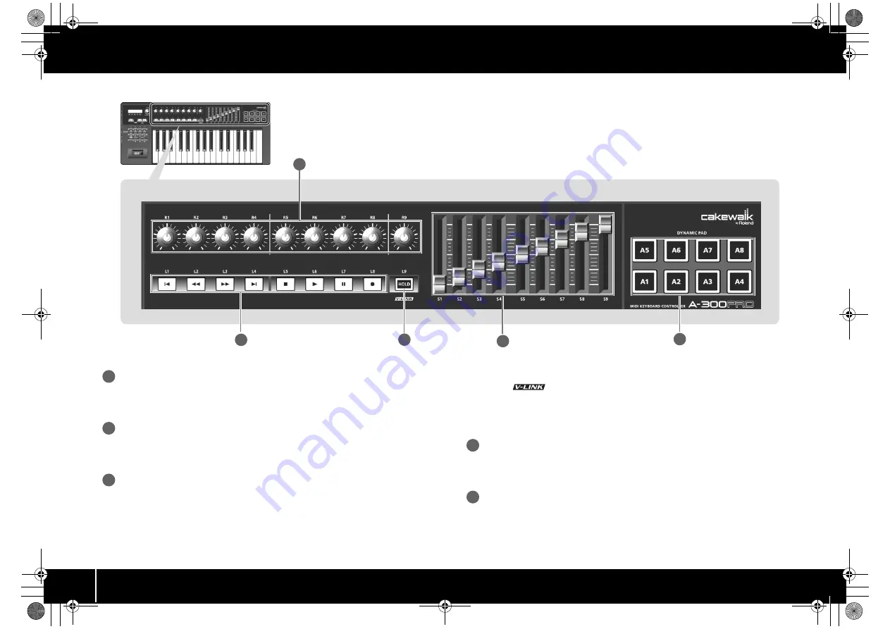
fig.Panel-Top.eps

Controllers [R1]–[R9] (knobs)

You can assign the desired MIDI messages to these knobs.

  “Assigning MIDI Messages” (p. 29)

Controllers [L1]–[L8] (button)

You can assign the desired MIDI messages to these buttons.

 “Assigning MIDI Messages” (p. 29)

[HOLD] button

This button turns Hold on/off (a function that sustains the note even after you release 
the [A1]–[A8] pad).
Alternatively, you can assign a desired MIDI message to this button or use it to turn 
V-LINK on/off instead of using it as Hold.

 “L9 FUNCTION” (p. 69)

V-LINK

V-LINK (

) is a function that allows music and images to be performed 

together. By using MIDI to connect two or more V-LINK compatible devices, you can 
easily enjoy a wide range of visual effects that are linked to the expressive elements of 
a music performance.

Controllers [S1]–[S9] (sliders)

You can assign the desired MIDI messages to these sliders.

 “Assigning MIDI Messages” (p. 29)

Controllers [A1]–[A8] (pads)

You can assign the desired MIDI messages to these pads.

 “Assigning MIDI Messages” (p. 29)

These pads can transmit velocity values that correspond to the force with which you 
pressed the pad, or aftertouch values.

13

14

15

11

12

11

12

13

14

15

A-300_500_800C_e.book  10 ページ  2010年2月22日 月曜日 午後9時13分

Summary of Contents for cakewalk A-300PRO

Page 1: ... 5 1 0 0 0 0 9 7 9 6 0 2 ...

Page 2: ...SB cable If you require a replacement for the supplied USB cable for example due to damage or loss please contact the nearest Roland Service Center or an authorized Roland distributor as listed on the separate sheet titled Information Owner s manual This is the document you re reading Keep it at hand for reference when needed Cakewalk Production Plus Pack installation guide This explains the insta...

Page 3: ... specific thing that must be done is indicated by the design contained within the circle In the case of the symbol at left it means that the power cord plug must be unplugged from the outlet The symbol alerts the user to important instructions or warnings The specific meaning of the symbol is determined by the design contained within the triangle In the case of the symbol at left it is used for ge...

Page 4: ...disconnect the power plug from the power outlet whenever the unit is to remain unused for an extended period of time Any accumulation of dust between the power plug and the power outlet can result in poor insulation and lead to fire 104 Try to prevent cords and cables from becoming entangled Also all cords and cables should be placed so they are out of the reach of children 106 Never climb on top ...

Page 5: ...cleaning wipe the unit with a soft dry cloth or one that has been slightly dampened with water To remove stubborn dirt use a cloth impregnated with a mild non abrasive detergent Afterwards be sure to wipe the unit thoroughly with a soft dry cloth 402 Never use benzine thinners alcohol or solvents of any kind to avoid the possibility of discoloration and or deformation Repairs and Data 452 Please b...

Page 6: ...l Maps 29 Assigning MIDI Messages 29 Checking the Assigned MIDI Messages 30 Receiving a Control Map from the A PRO 31 Transmitting a Control Map to the A PRO 31 Saving a Control Map on Your Computer 32 Loading a Control Map that was Saved on Your Computer 32 Message Parameters 33 Using Keyboard Sets 40 Receiving a Keyboard Set 40 Transmitting a Keyboard Set 40 Performing Play Mode 41 Playing the K...

Page 7: ...AFTERTOUCH CURVE 63 Clock related Settings 64 MIDI CLOCK ON OFF 64 MIDI CLOCK DEFAULT TEMPO 64 MIDI CLOCK OUTPUT PORT 64 USB related Settings 65 ADVANCED DRIVER MODE 65 MIDI related Settings 66 MIDI I F SWITCH 66 MIDI MERGE DESTINATION 67 Control Map Settings 68 STARTUP MEMORY 68 VALUE knob Settings 68 FUNCTION 68 Other Settings 69 H ACTIVITY ON OFF 69 L9 FUNCTION 69 OMNI 70 FACTORY RESET 70 Appen...

Page 8: ...lphanumeric characters When you operate a controller the value of the parameter assigned to that controller is shown for a certain duration Information such as the MIDI chan nel and program change is also shown PRM MUTE When the cursor is located here moving a controller will not transmit MIDI messages p 47 CTRL MAP When the cursor is located here you can turn the VALUE knob to switch between cont...

Page 9: ...R part UPPER button Use this button to play the UPPER part SHIFT button When you re in PLAY mode p 41 you can hold down the SHIFT button and use controllers B1 B4 the DUAL LOWER UPPER buttons the TRANSPOSE button and the OCTAVE buttons as a numeric keypad Hold down the SHIFT button and press the SPLIT button for backspace TRANSPOSE button This button lets you shift the pitch of the keyboard up or ...

Page 10: ...s Hold L9 FUNCTION p 69 V LINK V LINK is a function that allows music and images to be performed together By using MIDI to connect two or more V LINK compatible devices you can easily enjoy a wide range of visual effects that are linked to the expressive elements of a music performance Controllers S1 S9 sliders You can assign the desired MIDI messages to these sliders Assigning MIDI Messages p 29 ...

Page 11: ...desired MIDI message to these controllers Assigning MIDI Messages p 29 Use only the specified expression pedal EV 5 or EV 7 sold separately By connecting any other expression pedals you risk causing malfunction and or damage to the unit Security slot http www kensington com Side Panel DC Power on using the AC adaptor OFF Power off USB Power on with the USB cable connected USB i e bus power can be ...

Page 12: ...ROM drive When the auto play dialog box appears click Open folder to view files 4 In the appropriate folder within the CD ROM double click the Setup icon to start up the installer If you get a message saying The operating system you are using is not supported or The version of this file is not compatible with the version of Windows you re running or if you don t know the version of your operating ...

Page 13: ...A PRO Driver will be installed on your computer Click Next If any other message appears proceed as directed by the message 7 To begin the installation click Next once again Installation will begin fig win7securitya e eps_36 If a Windows security dialog box appears click Install 8 Turn the A PRO s POWER switch OFF 9 When the screen indicates Ready to install the driver use a USB cable to connect th...

Page 14: ...as been completed Click Close to close the A PRO Driver Setup dialog box If the System Settings Change dialog box appears click Yes Windows will automatically restart Now let s check to make sure that installation was successful Checking with a SONAR Soft Synths Windows p 19 A 300_500_800C_e book 14 ページ 2010年2月22日 月曜日 午後9時13分 ...

Page 15: ...PRO Driver will be installed on your computer Click Next If any other message appears proceed as directed by the message 6 To begin the installation click Next fig xpdrv2 e eps_27 If the Software Installation dialog box appears click Continue Anyway to continue the installation If you are unable to proceed click OK in the dialog box to terminate the installation Then change the setting as describe...

Page 16: ...e the setting as described in Driver signing option settings Windows XP p 80 and perform the installation once again 13 The screen will indicate Completing the Found New Hardware Wizard Click Finish 14 When installation is complete the A PRO Driver Setup dialog box will indicate Installation has been completed Click Close to close the A PRO Driver Setup dialog box If the System Settings Change dia...

Page 17: ... The screen will indicate Welcome to the A PRO Driver Installer Click Continue fig osx install e eps 6 If the screen asks you to select a destination click your start up disk to select it and then click Continue 7 When the display asks you to select the type of installation click Install or Upgrade 8 In the next screen click Continue Installation 9 When installation is completed click Restart to r...

Page 18: ... New Device you added and click Show Info 2 Enter the name in the Device Name field For each New Device enter the following names fig osxnewdevice e eps 18 Use the mouse to drag between the and symbols representing input and output respectively of A PRO and each New Device so that they are connected as shown in the illustration below fig osxmidiset e eps_32 19 Close the MIDI Studio dialog box or A...

Page 19: ...hat a problem has occurred Refer to Problems with Settings in the Troubleshooting section p 76 4 Click OK to close the dialog box 5 In the File menu click New The New Project File dialog box will appear 6 In the Template area choose Normal then enter a project name in the Name field and click OK fig sonarnew eps 7 In the Insert menu choose Soft Synths and then PSYN II 8 In the Insert Soft Synth Op...

Page 20: ...DI tab s MIDI Status field it may be that a problem has occurred Please refer to Problems with setup in the Troubleshooting section p 76 In System Preferences choose the Sound Output tab Make sure that your computer s main volume is not turned down or muted Also make sure that internal audio is selected If you re using headphones make sure that they are correctly connected to your computer s headp...

Page 21: ...vides 44 controllers you can freely assign a MIDI message to each controller For details refer to Using A PRO Editor p 22 Play Use ACT What is ACT ACT Active Controller Technology is functionality that lets you control SONAR from an external device such as the A PRO This lets you control the plug in effect or plug in synthesizer that s active in SONAR without having to make time consuming settings...

Page 22: ...a MIDI Message on the A PRO Keyboard p 48 1 Insert the included A PRO CD ROM into your CD ROM drive 2 On the CD ROM open the EDITOR folder and double click SETUP to start the installer 3 The screen Welcome to the InstallShield Wizard for A PRO Editor Setup will appear Click Next 4 When the Please Read screen appears read the contents and if you consent click Yes You cannot install A PRO Editor unl...

Page 23: ...alog box specify the MIDI devices as follows 5 Click OK to close the dialog box MIDI Port Assignments What is a MIDI port A MIDI port is a port used to transfer MIDI messages between your computer and the A PRO Input ports The output destination of the MIDI messages transmitted when you operate the A PRO s sliders knobs and buttons can be specified separately for each controller For details refer ...

Page 24: ...rol Map to the A PRO p 31 Transmit Receive Click Transmit to save a control map to the A PRO overwriting existing content Click Receive to load a control map from the A PRO fig editor04 num e eps fig editor05 num e eps The items in the window will differ depending on the controller and on the type of message being assigned Controller name This shows the name of the controller you re editing Assign...

Page 25: ...e editing is R1 R9 or S1 S9 you can make virtual center click settings p 55 This broadens the range in which the center value is transmitted Port Explanation Port 1 MIDI messages will be transmitted to A PRO 1 Port 2 MIDI messages will be transmitted to A PRO 2 Port 1 2 MIDI messages will be transmitted to both A PRO 1 and A PRO 2 Mode Explanation Unlatch Turns on when you press the button turns o...

Page 26: ... if you want to save a keyboard set on the A PRO Click Receive if you want to load a keyboard set from the A PRO Setting buttons Specify the button SPLIT DUAL LOWER for which you are assigning a keyboard set Close Closes the Keyboard Set window Keyboard Set Window 6 7 1 2 3 4 5 8 What is a Keyboard Set Keyboard related settings such as the MIDI channel and split point for the UPPER and LOWER parts...

Page 27: ...s of the File menu command Open View Assign list Displays the assigned MIDI messages in your Web browser Recently Used Files Shows the names of the recently used files Edit Menu Menu Explanation Copy Copies the setting of the selected controller to the clipboard Paste Pastes the setting from the clipboard to the selected controller No Assign Sets the MIDI assignment of the selected controller to N...

Page 28: ...d on the text Keyboard Shortcuts Command Key Windows Key Mac OS X File New Ctrl N Command N File Open Ctrl O Command O File Save Ctrl S Command S File Save As Ctrl Shift S Command Shift S File Exit Alt F4 Command Q Edit Copy Ctrl C Command C Edit Paste Ctrl V Command V Edit NO ASSIGN Del Del Next controller Ctrl F Command F Previous controller Ctrl B Command B A 300_500_800C_e book 28 ページ 2010年2月2...

Page 29: ...the type of MIDI message you want to assign fig editor assign3 eps 3 According to the type of MIDI message you selected use the fields of the message assignment area to specify the parameters For details on the parameters refer to Message Parameters p 33 fig editor assign4 eps 4 In the Output Port field specify the MIDI output port 5 If desired enter a name in the Name field 6 Click OK Using Contr...

Page 30: ...es If you want to see the current settings for each controller in the main window choose the Options menu command Show Messages and select the Show Assigned Messages check box The current assignments will be shown in simplified form as follows fig editor assignmessage eps The display color indicates the output port setting Checking the Assigned MIDI Messages Indication Meaning NO ASSIGN Note Chann...

Page 31: ...r When the dialog box disappears reception has been completed If you want to use the control map settings created in A PRO Editor on the A PRO keyboard use the following procedure to transmit the edited control map to the A PRO keyboard fig editor trans1 eps 1 In the Control Map dropdown list specify the number at which you want to save your control map 2 Click Transmit fig editor trans3 e eps_50 ...

Page 32: ...omputer in SMF format can be loaded into A PRO Editor To load an SMF file proceed as follows 1 Choose the File menu command Open 2 Specify the SMF file that you want to load and click Open An SMF file that does not contain A PRO control map data cannot be opened The SMF must contain settings for all controllers The contents of the Name field can be loaded only from an SMF that was saved by A PRO E...

Page 33: ...respondingcontrollerwillcontrolitsownoriginal function In this case the current channel will be used as the MIDI transmit channel Channel Message Assigns a channel message Use the Type field to select the type of message you want to assign According to the message you ve selected set the following parameters Note Assign a note message fig editor note eps Specify the following parameters Channel Pr...

Page 34: ...program number fig editor pc eps Specify the following parameters The range of the program number is 1 128 Item Content MIDI Channel MIDI channel Note Number Note number Min Value Lower value of key pressure Max Value Upper value of key pressure Item Content MIDI Channel MIDI channel Control Number Control number Min Value Lower limit of the control value Max Value Upper limit of the control value...

Page 35: ...e range of the program number is 1 128 Program Change Dec Assign the program change decrement function PC DEC This will transmit a program change number that is one less than the program change number most recently transmitted in the A PRO s program change mode fig editor pcdec eps Item Content MIDI Channel MIDI channel Min Number Lower limit of the program number Max Number Upper limit of the pro...

Page 36: ...d cannot be changed NRPN Assign a non registered parameter number fig editor nrpn eps Specify the following parameters The range for the data entry LSB is fixed at 0 127 and cannot be changed Item Content MIDI Channel MIDI channel RPN MSB RPN parameter number MSB RPN LSB RPN parameter number LSB MSB Min Value Lower limit of data entry MSB MSB Max Value Upper limit of data entry MSB Item Content MI...

Page 37: ... do anything System Realtime F6 Assign a system realtime message or F6 Tune Request fig editor realtime eps For System Realtime F6 use the Status field to choose the message you want to assign Item Content MIDI Channel MIDI channel Control Number Controller number Item Content F6 Tune request F8 Timing clock FA Start FB Continue FC Stop FF System reset A 300_500_800C_e book 37 ページ 2010年2月22日 月曜日 午...

Page 38: ...location and type If you use the automatic checksum calculation function use this special character to specify the point at which the checksum is to be inserted and its type S1 The most common type used by Roland and other man ufacturers S2 Choose this if a method other than S1 is used n Channel is any value between 0 7 If you want a channel number to be inserted in the exclusive message use this ...

Page 39: ...llowing limitations apply to the input You can t use a checksum You can t use a special character as the first byte You can also enter variable data using the special characters de scribed in Table 1 Special characters used in the message entry field p 38 If you use the special character DT use the Data Type field to specify the type of data Data Type If you ve used the special character DT in the...

Page 40: ...r When the dialog box disappears reception is complete If you want to use a keyboard set created in A PRO Editor on the A PRO keyboard proceed as follows to transmit it fig keyboardset1 eps 1 Use the SPLIT DUAL LOWER buttons to select the keyboard set that you want to edit fig keyboardsettrans eps 2 Click Transmit 3 In the confirmation box click Continue 4 A transmission progress dialog box will a...

Page 41: ...he settings of your sound module If you assign a MIDI message to the bender lever the pitch bend effect and modulation effect will be disabled Mode Explanation To select Play mode This is the mode in which you play the keyboard and operate the controllers MIDI messages will be transmitted by each con troller 1 Turn on the power 2 Exit EDIT mode Edit mode p 48 p 57 This is the mode in which you ass...

Page 42: ...ER UPPER buttons OCTAVE buttons 2 Press the ENTER button With this the numerical value you entered is confirmed What is OMNI If you turn OMNI on all controllers will transmit on the current channel regardless of their assigned MIDI transmit channel If you want the MIDI transmit channel of the controllers to also change when you switch the current channel turn OMNI on as follows 1 Press the ACT but...

Page 43: ...e s how to transmit bank select MSB LSB messages 1 Use the buttons to move the cursor to USER ASSIGN in the display The display will show the bank select number that was transmitted most recently 2 Use the VALUE knob to specify the desired bank select number Bank select MSB LSB messages will be transmitted Selecting Sounds PROGRAM CHANGE BANK Program change and bank select By using program change ...

Page 44: ...ed for UPPER The UPPER button will be lit when you turn on the power The entire keyboard will play the LOWER sound fig Lower e eps 1 Press the LOWER button so it s lit 2 Use the buttons to move the cursor to PGM CHANGE in the display 3 Turn the VALUE knob The LOWER sound will change When you play the keyboard you ll hear the sound specified for LOWER The assignment of the LOWER button can be chang...

Page 45: ...keyboard set window p 26 The SPLIT button lets you play the UPPER sound in the range of C4 and above while playing the LOWER sound in the range of B3 and below fig Split eps 1 Press the SPLIT button so it s lit If the cursor is at PGM CHANGE in the display turning the VALUE knob will change the UPPER sound To change the LOWER sound set Active Part p 62 to LOWER Then move the cursor to PGM CHANGE a...

Page 46: ... ASSIGN in the display The display will indicate the velocity value that was transmitted most recently 2 Use the VALUE knob to specify the desired velocity value TOUCH 1 127 fig lcd keyvelocity eps If the display indicates TOUCH the transmitted velocity value will correspond to the force with which you play the keyboard Refer to the system setting KEYBOARD VELOCITY CURVE p 60 Adjusting the Playing...

Page 47: ...rameter value to match the knob position with the parameter value before you perform 1 Press the buttons simultaneously The PRM MUTE cursor will light in the display 2 Operate a controller MIDI messages will not be transmitted even when you operate a controller 3 Once again press the buttons simultaneously The PRM MUTE cursor in the display will go dark Now MIDI messages will once again be transmi...

Page 48: ...AFTERTOUCH hold down the ACT button and button simultaneously and then apply strong pressure to the keyboard When you edit the assignment of a controller the assignment is saved automatically You can copy an assigned message to another controller or cancel an assignment For details refer to Copying an Assignment p 56 or Clearing an Assignment NO ASSIGN p 56 If you want to assign a system exclusive...

Page 49: ...L9 A1 A8 or HOLD P1 specify the desired Button mode setting p 55 If you assign a note message to R1 R9 S1 S9 or EXPRESSION P2 setting the controller to the maximum position will transmit a note message with the specified velocity value When you slightly lower the controller from its maximum position a note message with a velocity value of 0 will be transmitted If you assign a note message to B1 B4...

Page 50: ...ler will blink in the display 3 Verify that the display and press the ENTER button fig lcd aftertouch eps 4 Turn the VALUE knob until AFTERTOUCH appears in the display fig lcd midichannel eps 5 Press the ENTER button The display will indicate the currently specified MIDI transmit channel 6 Use the VALUE knob to specify the desired MIDI transmit channel 7 Press the ENTER button 8 Specify the Button...

Page 51: ... display will indicate the currently specified MIDI transmit channel 6 Use the VALUE knob to specify the desired MIDI transmit channel fig lcd ccnumber eps 7 Press the ENTER button The display will indicate the currently specified control change number 8 Use the VALUE knob to select the desired control change number 9 Press the ENTER button The display will indicate the currently specified control...

Page 52: ...eps 5 Press the ENTER button The display will indicate the currently specified MIDI transmit channel 6 Use the VALUE knob to specify the desired MIDI transmit channel fig lcd pcnumber eps 7 Press the ENTER button The display will indicate the currently specified program change number 8 Use the VALUE knob to select the desired program change number 9 Press the ENTER button If you ve assigned this m...

Page 53: ...e is the same as for RPN fig lcd midichannel eps 5 Press the ENTER button The display will indicate the currently specified MIDI transmit channel 6 Use the VALUE knob to specify the desired MIDI transmit channel 7 Press the ENTER button fig lcd rpnmsb eps 8 Use the VALUE knob to select the desired RPN MSB CC 101 or NRPN MSB CC 99 9 Press the ENTER button 10 Use the VALUE knob to select the desired...

Page 54: ...troller to which you want to assign tempo If the controller is a button press it The number of the selected controller will blink in the display 3 Verify that the display and press the ENTER button fig lcd tempo eps 4 Turn the VALUE knob until TEMPO appears in the display 5 Press the ENTER button If the controller is a button the tempo will be maximum 250 when on and minimum 20 when off Tempo Assi...

Page 55: ...n the value will be incremented by one or decremented by one if the minimum value is lower than the max imum value When the value reaches the maximum value minimum value it will wrap around to the minimum value maximum value The button will light only while held down Virtual center click setting In Edit mode when you assign a message to a knob R1 R9 or a slider S1 S9 as described in Assigning a MI...

Page 56: ...ig lcd copyfromto eps 4 Slightly move the copy source controller If it s a button press it The display will indicate the copy source and copy destination controller numbers 5 Verify in the display and press the ENTER button Here s how to clear the MIDI message assigned to a controller No MIDI message will be transmitted when you move a controller whose assignment was cleared If you clear the assig...

Page 57: ... Pads PAD VELOCITY CURVE Specifies how the velocity value transmitted when you strike a pad controller A1 A8 will correspond to the force with which you strike velocity curve 1 p 63 PAD AFTERTOUCH CURVE Specifies how the pad controllers A1 A8 will respond to aftertouch 1 p 63 Clock MIDI CLOCK ON OFF Specifies whether MIDI CLOCK will be transmitted OFF p 64 MIDI CLOCK DEFAULT TEMPO Specifies the in...

Page 58: ...y 500 ms OFF p 69 L9 FUNCTION Specifies the function of the HOLD button HOLD p 69 OMNI If OMNI is On all controllers will always transmit on the current channel regardless of the MIDI transmit channel setting that is assigned to the controller OFF p 42 FACTORY RESET Returns the A PRO to the factory set condition p 70 Category Item Contents Factory setting See page A 300_500_800C_e book 58 ページ 2010...

Page 59: ... CONTRAST and press the ENTER button 3 Use the VALUE knob to adjust the contrast This setting has a range of 1 10 Higher values make the display brighter 4 Press the ENTER button to return to Play mode LCD Contrast Setting LCD CONTRAST You can also change the LCD contrast in the following way fig numberbutton_edit eps In Edit mode press the following buttons to enter a numerical value Controllers ...

Page 60: ...ll be typical 3 1 HEAVY Higher velocity values volume will not be produced unless you play strongly 4 2 LIGHT Compared to curve 1 these curves allow greater volume change without having to play very strongly Higher velocity values volume can be produced even if you play softly 5 2 MEDIUM Keyboard sensitivity will be typical 6 2 HEAVY Higher velocity values volume will not be produced unless you pl...

Page 61: ... and press the ENTER button 4 Use the VALUE knob to select the desired KEYBOARD PORT The value of the selected setting is shown in the display 5 Press the ENTER button to return to Play mode KEYBOARD AFTERTOUCH CURVE Number Curve type Explanation 1 This is the most typical curve The pressure you apply to the keyboard and the resulting aftertouch effect will corre spond in the most natural way 2 Co...

Page 62: ...YBOARD PAD and press the ENTER button fig lcd TRANSPOSE eps 3 Use the VALUE knob to select TRANSPOSE and press the ENTER button fig lcd TRANSPOSE1 eps 4 Use the VALUE knob to specify the transposition value You can specify a value in the range of 6 to 5 semitones 5 Press the ENTER button to return to Play mode This specifies whether the SHIFT button will operate in Unlatch mode On when held down O...

Page 63: ...CURVE The number of the selected setting is shown in the display 5 Press the ENTER button to return to Play mode Pad related Settings PAD VELOCITY CURVE Number Type of curve Result 1 This is the most typical curve The force with which you strike the pad will correspond to the volume in the most natural way 2 Compared to curve 1 there will be greater volume change for softer strikes on the pad 3 Pa...

Page 64: ...fy the MIDI CLOCK DEFAULT TEMPO value in a range of 20 250 The display will indicate the value you specified 5 Press the ENTER button to return to Play mode This setting specifies the port from which MIDI clock will be output when MIDI CLOCK ON OFF is On 1 Simultaneously press the ACT button and the button 2 Use the VALUE knob to select MIDI CLOCK and press the ENTER button fig lcd CLKOUTPUTPORT e...

Page 65: ...USB MIDI driver type FPT Fast Processing Technology of MIDI Transmission This takes full advantage of the USB bandwidth to process MIDI data in an optimal way at all times depending on the amount of MIDI data to be transmitted 5 Press the ENTER button to return to Play mode USB related Settings ADVANCED DRIVER MODE Setting Explanation OFF Choose this if you want to use the standard MIDI driver pro...

Page 66: ...hanged between the A PRO and the computer and between the A PRO and the external MIDI device ON The A PRO keyboard s MIDI connectors will operate as a MIDI interface MIDI messages from the computer connected via USB to the A PRO will be transmitted to a sound module connected to the A PRO s MIDI OUT connector MIDI messages from a MIDI device connected to the A PRO s MIDI IN connector will be sent ...

Page 67: ...R button to return to Play mode MIDI MERGE DESTINATION Number Setting Explanation 1 PORT1 Messages received at MIDI IN will be merged into the A PRO s PORT 1 2 PORT2 Messages received at MIDI IN will be merged into the A PRO s PORT 2 3 MIDI OUT Messages received at MIDI IN will be merged into the A PRO s MIDI OUT MIDI MERGE switch and MIDI MERGE DESTINATION fig MIDI MERGE eps In this illustration ...

Page 68: ...arameter use the VALUE knob to specify the desired control change number 6 Press the ENTER button Control Map Settings STARTUP MEMORY Setting Explanation CTL MAP 0 Control map number 0 will be selected at start up LAST ACC MAP The control map that was last selected and saved will be called up upon start up VALUE knob Settings FUNCTION Value Setting Explanation Value range 1 KEY VELOCITY Fixes the ...

Page 69: ...button This specifies the function of the HOLD button 1 Simultaneously press the ACT button and the button 2 Use the VALUE knob to select SYSTEM SETTING and press the ENTER button fig lcd L9FUNC eps 3 Use the VALUE knob to choose L9 FUNCTION and press the ENTER button fig lcd L9FUNC1 eps 4 Use the VALUE knob to specify the function of HOLD button 5 Press the ENTER button Other Settings H ACTIVITY ...

Page 70: ...URE will appear blinking in the display fig lcd RESETSURE eps 3 If you are sure that you want to execute the factory reset operation press the ENTER button FACTORY RESET will appear blinking in the display while the factory reset operation is being carried out Once the factory reset is complete COMPLETE will appear in the display You ll then be returned to Play mode OMNI FACTORY RESET A 300_500_80...

Page 71: ... DAW software Since the A PRO has two MIDI output ports you can use one port to play sounds and control the sound module while using the other port to control your DAW software fig MIDI port3 e eps For example if you want to use the A PRO s A1 A8 buttons to switch sounds on your sound module and use the S1 S9 sliders to control the volume faders of your DAW software s mixer you could assign the co...

Page 72: ...to your MIDI sound module 4 Set the A PRO s current channel to match the MIDI receive channel of your MIDI sound module 5 When you play the keyboard your MIDI sound module will produce sound Connecting the A PRO Directly to a Sound Module MIDI sound module sold separately MIDI IN Indicator DC IN MIDI OUT AC adaptor sold separately 921 To prevent malfunction and or damage to speakers or other devic...

Page 73: ...Windows 7 Windows Vista users The A PRO s MIDI input output device cannot be used by the Media Player included with Windows 7 Vista Windows XP users Mac OS X users To specify the MIDI input output settings for Mac OS X perform the Audio MIDI settings described in step 13 and following of Mac OS X Users p 17 About Standard Driver Mode Installing the Standard Driver Input output Device Settings MIDI...

Page 74: ...e there any devices labeled Other Unknown or X in the Device Manager If driver installation was not completed successfully the partially installed driver may remain in an incomplete state Reinstall the A PRO driver as described in Reinstalling the driver p 80 Did you log on to Windows with the appropriate user privileges You must log onto Windows using one of the following user names A user name b...

Page 75: ...gement settings p 81 Does your computer meet the requirements of the USB specification Operation may be unstable if your computer does not meet the electrical requirements of the USB specification In this case you may be able to solve the problem by connecting a self powered USB hub a USB hub that has an internal power supply or an AC adaptor Could you have connected the A PRO to a different USB c...

Page 76: ...hen turn it back on again If this does not solve the problem restart your computer Could you have disconnected and reconnected the USB cable while using the A PRO Close all software that s using the A PRO Next switch off the A PRO s power then turn it back on again If this does not solve the problem restart your computer Could the A PRO have been connected when the computer started up On some comp...

Page 77: ... To change or check this setting proceed as directed in Changing or verifying the driver settings Windows p 80 Changes to this setting will take effect after you turn the A PRO s power off then on again Unless you are experiencing problems you should leave this check box cleared the default state Try disabling the LAN In your computer s Device Manager try disabling LAN wired wireless If this elimi...

Page 78: ...he sound of the software synthesizer can be heard as actual sound from the sound card Regardless of the combination of software synthesizer and sound card there will always be some latency but by using the appropriate combination of software and sound card together with the correct settings it is often possible to shorten latency to the point that it causes no problems in practice In general the f...

Page 79: ...tart Windows Mac OS X users The displayed content may differ depending on your system 1 Start up your computer with all USB cables disconnected Make sure that all USB cables other than those for a USB keyboard and USB mouse are disconnected 2 Insert the included A PRO CD ROM into the CD ROM drive of your computer 3 Double click one of the following icons on the CD ROM to start up the uninstaller 4...

Page 80: ...leave this check box cleared If you change this setting it will take effect after you ve turned the A PRO s power off then on again Show README button This displays the online manual for the driver Information This displays the version of the currently installed driver Driver installation may not be possible due to your settings for Driver Signing Options Refer to the following and make the approp...

Page 81: ...Maintenance and then click Power Options If you re using the Classic view double click the Power Options icon 2 In Select a power plan choose High performance 3 In the High performance area click Change plan settings 4 Click Change advanced power settings 5 In Power Options Advanced Settings click the symbol for Hard Disk and click the symbol for Turn off hard disk after to open it 6 Click Setting...

Page 82: ...Maintenance and click System If you re using the Classic view double click the System icon 2 In the list of tasks shown at the left click Advanced System Settings 3 A User Account Control dialog box will appear click Continue If you re asked to enter an administrator password log on to Windows as a user whose account type is administrator and make the setting again 4 Click Performance Settings and...

Page 83: ...lock Command All Sound Off Reset All Controller Local control All Notes Off Active Sense Reset 1 1 16 Mode 3 OMNION OFF MONO POLY O 9n v 1 127 O 8n v 1 127 9n v 0 0 127 O O O O X O 0 127 O O O 0 127 O O O O 1 120 O 1 121 O O 1 123 O O X X X X X X X X X X X X X X O X X X X X X X X X X X 1 Transmits When the Panic function is executed Model A 300PRO 500PRO 800PRO Date Jan 16 2010 Version 1 00 Mode 1...

Page 84: ...N OUT USB Connector DC IN Jack Power Supply DC 9 V AC Adaptor or USB Bus Power Current Draw 300 mA AC Adaptor 300 mA USB Bus Power Dimensions A 300PRO 605 9 W x 250 8 D x 91 4 H mm 23 7 8 W x 9 7 8 D x 3 5 8 H inches A 500PRO 838 9 W x 250 8 D x 91 4 H mm 33 1 16 W x 9 7 8 D x 3 5 8 H inches A 800PRO 1001 9 W x 250 8 D x 91 4 H mm 39 1 2 W x 9 7 8 D x 3 5 8 H inches Weight A 300PRO 2 9 kg 6 lbs 7 ...

Page 85: ...ied 56 Copy 27 Copying an Assignment 56 Current Channel 42 D DC 11 DC IN Jack 11 72 Display 8 Driver Signing Options Settings 80 DUAL 45 DUAL Button 9 E Edit Menu 27 EDIT Mode 48 Edit Mode 41 Encoder Simulate 37 ENTER Button 8 Export Assign List 27 EXPRESSION 11 EXPRESSION P2 Jack 11 F F6 37 FACTORY RESET 58 70 Free Message 24 39 FUNCTION 57 H H ACTIVITY 69 H ACTIVITY ON OFF 58 Help Menu 27 HOLD 1...

Page 86: ... OMNI 42 58 Open 27 Options Menu 27 Output Port 23 25 29 P Pad 10 63 PAD AFTERTOUCH CURVE 57 63 PAD VELOCITY CURVE 57 63 Paste 27 Performing 41 Pitch 9 Pitch Bend 41 Play Mode 41 Playing Dynamics 46 Polyphonic Key Pressure 25 34 Port 23 Power Switch 11 PRM MUTE 47 PROGRAM CHANGE 43 Program Change 34 35 Program Change Dec 35 Program Change Inc 36 Program Change Min Max 35 Program Change Assignment ...

Page 87: ...he driver Mac OS X 79 Windows 79 UNLATCH 55 Unlatch 25 UPPER 44 45 UPPER Button 9 USB 11 USB Cable 2 USB Connector 11 V 8 46 VELOCITY 46 Velocity Curve 60 Velocity Responds 46 Vibrato 9 41 View Assign list 27 Viewing an assignment list 30 Viewing the assigned messages 30 Virtual Center Click 55 V LINK 10 A 300_500_800C_e book 87 ページ 2010年2月22日 月曜日 午後9時13分 ...

Page 88: ...coloured BROWN must be connected to the terminal which is marked with the letter L or coloured RED THIS APPARATUS MUST BE EARTHED THE WIRES IN THIS MAINS LEAD ARE COLOURED IN ACCORDANCE WITH THE FOLLOWING CODE GREEN AND YELLOW EARTH BLUE NEUTRAL BROWN LIVE For the U K For the USA DECLARATION OF CONFORMITY Compliance Information Statement Model Name Type of Equipment Responsible Party Address Telep...

Page 89: ...rantee that interference will not occur in a particular installation If this equipment does cause harmful interference to radio or television reception which can be determined by turning the equipment off and on the user is encouraged to try to correct the interference by one or more of the following measures Reorient or relocate the receiving antenna Increase the separation between the equipment ...

Page 90: ...For EU Countries A 300_500_800C_e book 90 ページ 2010年2月22日 月曜日 午後9時13分 ...

Page 91: ...nly the included USB cable If you require a replacement for the supplied USB cable for example due to damage or loss please contact the nearest Roland Service Center or an authorized Roland distributor as listed on the separate sheet titled Information Owner s manual This is the document you re reading Keep it at hand for reference when needed Cakewalk Production Plus Pack installation guide This ...

Page 92: ... 5 1 0 0 0 0 9 7 9 6 0 2 ...

Reviews: