


Description
R&S
®
TS-PWA3
19
User Manual 1157.8143.12 ─ 17
pactTSVP, so plug-in modules for the R&S PowerTSVP can also be operated in the
R&S CompactTSVP.
Connector X0 (P47) serves as a power interface for a cPCI standard PSU. An addi-
tional PSU can be plugged onto an optional power backplane, in which case the con-
nection with the control backplane is made with an ATX power supply cable.
Support for the Rear I/O concept according to Standard IEEE 1101.11-1998 is imple-
mented for P20. Voltages up to 125 VDC can be routed in the Rear I/O area.
The PXI trigger bus according to PXI R2.0 is also implemented.
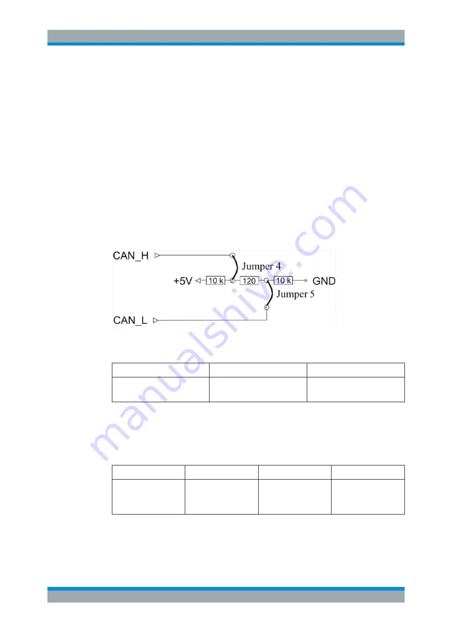
The
CAN bus
(according to standard CAN 2.0b (1Mbit)) is integrated as the manage-
ment bus, and is available at all slots. Signals CAN_L and CAN_H can be terminated
with jumpers and resistors (
). Instead of being terminated, the bus can be
extended externally using the extension connector X80.
If the optional R&S TS-PXB2 backplane extension is used, the CAN bus is also availa-
ble at slots A1 and A2. The R&S TS-PXB2 is connected to the main backplane via
X80. The use of the backplane extension does not change the termination principle.
Figure 3-9: CAN Bus Termination
Table 3-3: CAN Bus
Number Lines
U max (VDC)
Pin
2
5
CAN_H: P20/C1
CAN_L: P20/D1
Two additional
external signals
(e.g. supply voltages) can be fed in via a plug-in mod-
ule in P20. This input can come from an internal AC/DC module or from other external
signal sources. One way in which this feature can be used is to provide a primary volt-
age for generating local supply voltages (DC/DC converter).
Table 3-4: External Additional Signals
Number Lines
U max (VDC)
Imax/Slot(ADC)
Pin
2
60
2
input for ext. signals:
P20: AUX1 B20, E19
P20: AUX2 A20, D19
Lines with +5 V and +12 V are taken from connector X0 (P47) to optional threaded
studs. This makes it easy to connect AUX1 to +5 V and AUX2 to +12 V, e.g. using an
optional bus bar or cable (see Figure 3-10).
Construction


