Instrument tour
R&S
®
SGT100A
33
Getting Started 1419.4576.02 ─ 10
5
Instrument tour
This chapter explains the control elements and the connectors of the R&S
SGT.
The views of the front panel and the rear panel help you to get familiar with the
instrument and to perform first steps. For specifications of the interfaces, see the
data sheet.
The meanings of the labels on the R&S
SGT are described in
5.1
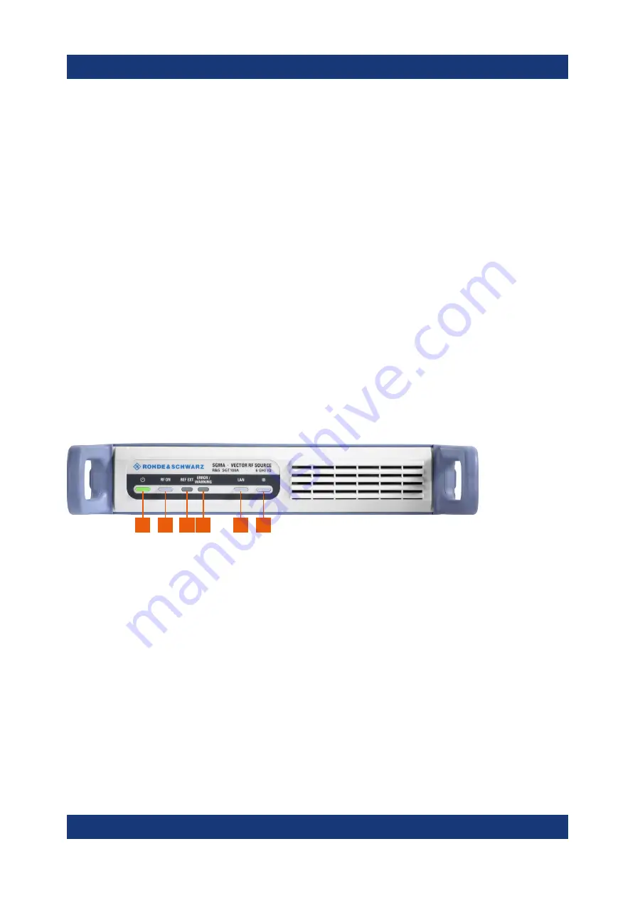
Front panel tour
This section provides an overview of control elements on the front panel of the
R&S
SGT. The front panel contains LEDs to inform you about the status of the
instrument, in particular for remote control of the R&S
SGT.
The connectors of the R&S
SGT are on the
1
2
3 4
5
6
Figure 5-1: R&S
SGT front panel controls
1 =
2 =
3 =
4 =
5 =
6 =
[POWER ON/STANDBY]
The [POWER ON/STANDBY] key switches the instrument from the standby to the
ready state or vice versa.
The LED above the [POWER ON/STANDBY] key indicates the instrument state,
see
How to:
●
Chapter 4.10, "Switching on or off"
Front panel tour


