


PowerFlex Digital DC Drive User Manual -
Publication 20P-UM001C-EN-P - July 2008
Installation and Wiring
1-25
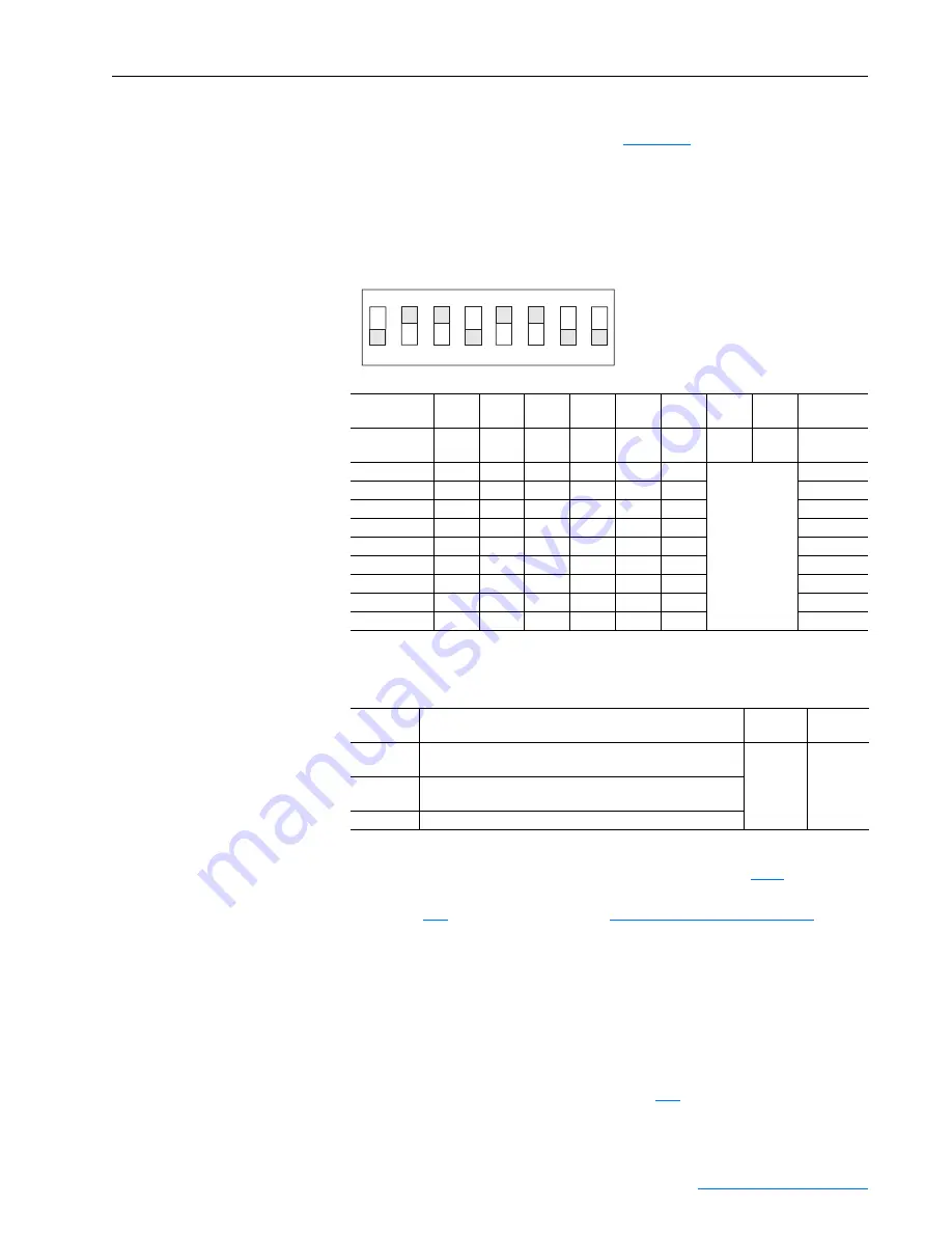
Compare the field current value of the motor to the rated value of the
internal field converter of the drive (see
below) and set switch
S14 to the closest value.
Note: The configuration of switch S14 is not required if the motor’s field
control is provided via an external source, however, in this case it is
recommended that the switch settings be completed as described above.
Table 1.G DIP Switch S14 Field Current Configuration Settings
Relay Outputs
Terminals 35 and 36 and 75 and 76 are N.O. relay outputs. The relay output
between terminals 35 and 36 is configured with parameter
[Relay Out
1 Sel]. The relay output between terminals 75 and 76 is configured with
parameter
[Relay Out 2 Sel]. See
for
more information.
Thermistors and Thermal Switches
To detect motor overheating and protect the motor from overloading, an
external, user-supplied thermistor (PTC) or thermal switch must be
connected to terminals 78 and 79. The drive’s response to a motor over
temperature fault is configured in parameter
[OverTemp Flt Cfg]. If a
temperature sensor is not used, a 1k ohm resistor must be connected
Switch ohms 148
330
182
36.4
845
1650
Equivalent
Resistance
Field current
scale
S14-1
S14-2
S14-3
S14-4
S14-5
S14-6
S14-7
S14-8
1.0 A
OFF
OFF
OFF
OFF
OFF
ON
Not used
1650 ohm
2.0 A
OFF
OFF
OFF
OFF
ON
OFF
845 ohm
3.0 A
OFF
OFF
OFF
OFF
ON
ON
558.8 ohm
5.0 A
OFF
ON
OFF
OFF
OFF
OFF
330 ohm
10.0 A
ON
OFF
OFF
OFF
OFF
OFF
168 ohm
12.9 A
ON
OFF
OFF
OFF
ON
ON
129.2 ohm
17.2 A
OFF
ON
ON
OFF
ON
ON
97 ohm
20.0 A
ON
OFF
ON
OFF
OFF
ON
83 ohm
24.1 A
ON
ON
ON
OFF
OFF
OFF
69 ohm
Terminals
Description
Maximum
Voltage
Maximum
Current
35, 36
Normally open contact. Configured with parameter 1392 [Relay
Out 1 Sel] - set to 25 “Contactor” by default.
250V AC
1A
75, 76
Normally open contact. Configured with parameter 629 [Relay
Out 2 Sel] - set to 5 “Ready” by default.
78, 79
Motor thermistor connections (PTC)
1
ON
2
3
4
5
6
7
8
DIP
Note: Illustration is an example
configuration only. DIP switch S14 must be
set
≥
the rated field current specified on
the motor nameplate or possible motor
damage may result.