12
Rockwell Automation Publication 750-AT006D-EN-P - January 2022
Chapter 1 Background
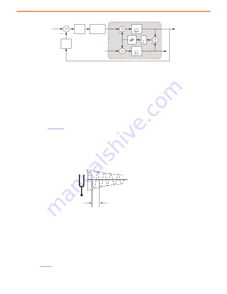
Figure 7 - Backlash Model
The severity of this problem increases with the following:
•
As the backlash distance increases, the resonant frequencies decrease.
•
As the load ratio increases, the step in inertia becomes larger. Because the load is intermittently disconnected from the motor, this
step is called the load disconnect ratio:
If the velocity regulator is tuned for peak performance, the velocity regulator response is under-damped at best and unstable at worst.
Typically, the motor shaft oscillates wildly between the limits that are imposed by the backlash distance. The net effect is an audible buzzing
sound when the motor is at rest, commonly referred to as chatter. Resonances occur at the fundamental frequency of this chatter and its
harmonics. If this situation persists, the coupling or gearbox wears out prematurely.
, describes the effects of compliance and backlash and how to control them.
Resonances
Resonance is the tendency for a system output to oscillate with greater magnitude at some frequencies than at the others. Resonant
frequencies are frequencies where the magnitude is at a relative maximum. Here, the system is sensitive to input and the gain is very high.
Resonances are difficult to control because even small input forces can produce large magnitude oscillations in the output.
Figure 8 - Tuning Fork Resonance
Anti-resonant frequencies are frequencies where the magnitude is at a relative minimum. Here, the system does not respond well to input
and the gain is very low. Anti-resonances are difficult to control because even large input forces can produce little or no response in the
output.
Compliance and backlash create resonances. Increasing the load inertia makes these problems worse. As a result, mechanical loads exhibit
resonances that limit performance, damage hardware, consume energy, and generate noise. It is often left to the user to suppress these
resonances through manual tuning, a challenging and time consuming task. Resonances typically increase in number and severity as
controller gains are increased. They range in frequency from a few Hz to a few thousand Hz. A typical approach is to reduce regulator gains
to a low enough level so that the system bandwidth falls below the lowest resonant frequency. However, this approach results in limited
performance.
There are two main types of resonances: motor side resonances and load side resonances. Motor side resonances are further broken down
into three subtypes based on their frequency range: Low Frequency (LF) resonances, Mid Frequency (MF) resonances, and High Frequency
(HF) resonances.
shows the types of resonances.
V
M
V
CMD
1
Power
Converter
T
m
PI
LPF
1
V
L
Velocity Loop
1
T
D
T
R
JT
JM
-------
R
1
+
=
T
dB
Time [s]
FREE VIBRATION
Frequency [Hz] = 1/(2
S
*T)


