


Rockwell Automation Publication LDAT-UM001A-EN-P - April 2016
35
Commission
Chapter 4
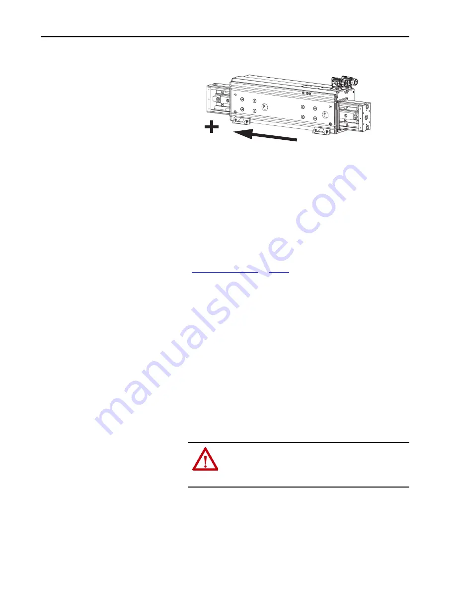
Figure 9 - Positive Motion Direction
Configure and Commission
Your SERCOS Servo Drive with
Logix Designer Application
For each linear thruster powered by a Kinetix 2000, Kinetix 6000,
Kinetix 6200, or an Ultra3000 servo drive, use the next four sections to
configure, hookup test, tune, fine-tune and configure homing for the linear
thruster.
These procedures assume the linear thruster and a Kinetix 2000, Kinetix 6000,
Kinetix 6200, or an Ultra3000 servo drive have been installed and wired as one
axis of the motion system.
For help using the Logix Designer application to configure your linear thruster,
refer to
. This procedure assumes you are
familiar with the Logix Designer application.
Configure
Follow these steps to configure your drive for the linear thruster.
1. Loosen shipping and handling set screw until it is flush with the stator
body surface.
2. Run the Logix Designer application.
3. Complete the basic system configuration to create an axis.
4. Right-click on your axis and select Properties.
5. Set these values in the appropriate Axis Properties tab of the Logix
Designer application
ATTENTION:
Incorrect parameter settings can result in uncontrolled
motion, with the potential for damage to the linear thruster. If the
Positioning Mode is set to Rotary, damage to the linear thruster or
the machine due to incorrect positioning can occur.