background image

B-2

Accessories and Dimensions

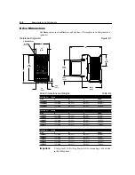
Accessory Dimensions

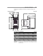
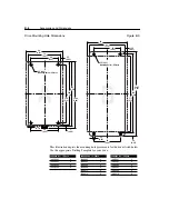
All dimensions are in millimeters and (inches). Dimensions are not used for 
manufacturing purposes.

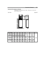
Dynamic Brake Modules

Figure B.1

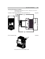
Bulletin 1321 Line Reactors

Figure B.2

Catalog No.

A

B

160-BMA1 

&

 160-BMB1

245 (9.64)

225 (8.86)

160-BMA2 

&

 160-BMB2

334 (13.15)

314 (12.36)

Catalog No.

A

B

C

D

E

1321-3R2-A

112 (4.4)

104 (4.1)

74 (2.9)

50 (2.0)

37 (1.44)

1321-3R2-B

112 (4.4)

104 (4.1)

74 (2.9)

50 (2.0)

37 (1.44)

1321-3R4-A

112 (4.4)

104 (4.1)

76 (3.0)

50 (2.0)

37 (1.44)

1321-3R4-B

112 (4.4)

104 (4.1)

76 (3.0)

50 (2.0)

37 (1.44)

1321-3R8-A

152 (6.0)

127 (5.0)

76 (3.0)

53 (2.1)

51 (2.0)

1321-3R8-B

152 (6.0)

127 (5.0)

76 (3.0)

53 (2.1)

51 (2.0)

1321-3R12-A

152 (6.0)

127 (5.0)

76 (3.0)

53 (2.1)

51 (2.0)

1321-3R18-A

152 (6.0)

133 (5.3)

79 (3.1)

51 (2.0)

51 (2.0)

GND

+

BR

BR

WARNING

DANGER

DANGER

BR

+

BR

GND

50

(1.97)

72

(2.83)

86.4

(3.4)

B

A

6.86 (0.27)

Mounting Holes – 4 Places –

8 (0.315)

7.5

(0.3)

14

(0.55)

29

(1.14)

B

E

D

C

A

Summary of Contents for Allen-Bradley 160 SSC Series

Page 1: ...160 SSC Variable Speed Drive Series C 0 37 4 0 kW 0 5 5 HP FRN 7 03 FRN 7 04 FRN 7 05 FRN 7 06 User Manual ...

Page 2: ...many variables and requirements associated with any particular installation Rockwell Automation cannot assume responsibility or liability for actual use based on the examples and diagrams No patent liability is assumed by Rockwell Automation with respect to use of information circuits equipment or software described in this manual Reproduction of the contents of this manual in whole or in part wit...

Page 3: ...ting 7 which allows for the frequency source to be switched from the control terminal block TB3 to the P58 Internal Frequency setting New Output Configuration Setting P47 Output Configure has a new setting When setting 10 is selected the output will be active when the Power Factor Angle is above the P48 Output Threshold setting Additional Compensation Mode P78 Compensation has an additional mode t...

Page 4: ...ware Version FRN 2 0 or earlier are not compatible with the Bulletin 160 Series C drives Series C drives must use DeviceNet modules Catalog No 160 DN2 The 160 DN2 module is also compatible with Series A and B drives with the exception of the Series A Preset Speed model with Firmware Version FRN 4 04 24V DC Interface Bulletin 160 Series C drives must use a Series B or later 24V DC Interface module ...

Page 5: ... Power Wiring 2 2 Precautions 2 2 Terminal Blocks 2 2 Terminal Block Wiring 2 3 Specifications 2 3 Motor Branch Circuit Analysis 2 4 Branch Circuit Protective Devices 2 5 Input Power Conditioning 2 6 Motor Cable Types 2 6 Long Motor Cable Effects 2 7 Control Wiring 2 9 Requirements 2 9 Specifications 2 9 Important Precautions 2 9 Control Wiring Considerations 2 10 Control Methods and Selection Gui...

Page 6: ...ol Setup and Activation 5 17 Wire For PI Control 5 17 Program for PI Control 5 17 Tune the PI Loop 5 18 Common Problems with PI Control 5 19 Troubleshooting Fault Information 6 1 How to Clear a Fault 6 1 Specifications A 1 Accessories and Dimensions B 1 Accessory Dimensions B 2 Drive Dimensions B 6 CE Conformity CE Compliance C 1 Essential Requirements for a Conforming EMC Installation C 1 General...

Page 7: ...allation start up and subsequent maintenance of the system Failure to comply may result in personal injury and or equipment damage ATTENTION The surface temperatures of the drive may become hot which may cause injury ATTENTION This drive contains ESD Electrostatic Discharge sensitive parts and assemblies Static control precautions are required when installing testing servicing or repairing this as...

Page 8: ...Bulletin 160 drive follows as an aid for nameplate interpretation Refer to Figure 1 1 and Figure 1 2 Important Before you install and start up the drive inspect for mechanical integrity Look for loose parts wires and connections Identifying Your Drive Catalog Number The figure below describes the 160 SSC catalog numbering scheme Catalog Number Explanation Figure 1 1 Amperage ratings vary based on ...

Page 9: ...e brackets 160 AA02NSF1P1 SERIES C ANALOG S F FRN 7 XX IP20 Allen Bradley MADE IN U S A 0 37KW 0 5 HP Motor Rating I N P U T O U T P U T V 200 240 3 Ø A 2 8 Hz 50 60 VA 1100 V 200 230 3 Ø A 2 3 Hz 0 240 S N XXXXXXXX XXXXX OPERATING AMBIENT TEMP 0 50 C SHORT CIRCUIT CURRENT 100 KA POWER TERMINAL WIRE Use 75 C Cu Wire 4 mm2 75 mm2 12 18 AWG Torque 1 35 Nm 12 in lbs C US UL LISTED IND CONT EQ 966X Ca...

Page 10: ...fer to Chapter 6 for details on how to clear a fault and general troubleshooting procedures Ready Indicator LED illuminates when the DC bus is charged and the drive is ready to run DC Bus Test Points provide easy access for test probes when measuring DC Bus voltage Cooling Fan provides air flow across heatsink fins to prevent overheating Not required on 37 or 55 kW 5 or 75 HP ratings DIN Latch pro...

Page 11: ...lity DeviceNet Communication Module option allows control and monitoring of parameters via a DeviceNet network RS 232 Communication Module option allows control and monitoring of parameters via a RS 232 network Remote Programming Adapter option allows connection to Remote Keypad Module or Copycat Keypad Module via cable 1 to 3 meters 24V DC Interface Module option allows you to command the drive w...

Page 12: ...1 6 Getting Started End of Chapter ...

Page 13: ...thod is not available on 4 0 kW 5 HP three phase or 1 5 kW 2 HP single phase models See Appendix B for details on drive dimensions and weights Clearances Maintain 12 5 mm 0 5 in clearance at the top bottom and front of all drives Clearance requirements between units varies by model 2 2 kW 3 HP 230V 460V Drives Provide a minimum of 8 5 mm 0 33 in clearance between units All Other Drive Ratings No c...

Page 14: ... signals that will start and stop the motor A device that routinely disconnects then reapplies input power to the drive for the purpose of starting and stopping the motor should not be used If it is necessary to use this method for starting and stopping or if frequent cycling of power is unavoidable make sure that it does not occur more than once a minute ATTENTION Do not connect power factor corr...

Page 15: ...ive devices IEC Class 10 overload An external overload relay is not required for single motor applications as long as the Drive kW HP rating is less than three times larger than the motor kW HP rating Each terminal supports up to 2 wires of approved gauge Model Screw Size Max Min Wire Size mm2 AWG Max Min Torque Nm lb in 4 0 kW 5 HP M4 5 26 3 31 10 12 1 35 0 90 12 8 All Other Ratings M4 3 31 0 82 ...

Page 16: ...ypes See Table 2 D for recommended cable types Reflected Wave Protection The use of a drive may result in increased peak to peak voltage at the motor See Table 2 E for an explanation of motor insulation limitations versus cable lengths Capacitive Current Coupling High speed voltage switching causes AC coupling from motor cables to ground terminal protective earth See Table 2 F for cable length rec...

Page 17: ...oup motor installations the Bulletin 140 can be used for protection of an individual motor within the group and one set of fuses or a UL489 rated circuit breaker serves as the Branch Circuit Protective Device for the entire Group Installation Bulletin 140M manual motor starters can be used in single and group motor applications without additional short circuit protection Refer to the technical sup...

Page 18: ...r conductor with the ground lead and shield if using shielded cable connected to the drive ground terminal and the motor frame ground terminal Table 2 D provides the recommended wire type for both wet and dry installations as defined by NEC 1996 70 31 These recommendations are based upon a variety of factors such as insulation thickness susceptibility to moisture and susceptibility to nicks and cu...

Page 19: ...tive current recommendations 380 460V Ratings Motor Insulation Rating Motor Cable Only RWR at Drive Reactor at Motor Shielded Unshielded Shielded Unshielded Shielded Unshielded feet meters feet meters feet meters feet meters feet meters feet meters 4 0 kW 5 HP 1000 Vp p 45 13 7 20 6 1 525 160 600 183 325 99 1 300 91 5 1200 Vp p 90 27 4 40 12 2 525 160 600 183 525 160 425 130 1600 Vp p 525 160 475 ...

Page 20: ...5 HP 2 350 107 600 183 300 91 5 600 183 400 122 600 183 4 425 130 600 183 350 107 600 183 450 137 600 183 8 475 145 500 152 450 137 500 152 2 2 kW 3 HP 2 360 110 600 183 280 85 4 600 183 400 122 600 183 4 375 114 600 183 275 83 8 600 183 400 122 600 183 8 400 122 500 152 400 122 500 152 1 5 kW 2 HP 2 300 91 5 550 168 275 83 8 600 183 300 91 5 600 183 4 300 91 5 550 168 275 83 8 600 183 300 91 5 50...

Page 21: ... G Important Precautions Terminal Block Max Min Wire Size mm2 AWG Max Min Torque Nm lb in TB3 2 5 0 5 14 22 0 8 0 4 8 4 ATTENTION The drive is supplied with an internal 12V supply Dry contact or open collector inputs are required for discrete control inputs If an external voltage is applied component damage could occur ATTENTION The drive start stop and enable control circuitry includes solid stat...

Page 22: ...t closure or open collector input required Refer to Appendix A for solid state control input specifications If both Run Forward and Run Reverse inputs are closed at the same time an undetermined state could occur Controlsignalcablelengthishighlydependentonelectricalenvironmentandinstallationpractices To improve noise immunity TB3 Common must be connected to ground terminal protective earth For con...

Page 23: ...nd the drive to run or stop PI Control Firmware Version FRN 7 06 allows activation of PI control in P46 Input Mode settings 0 through 7 and 9 listed in Table 2 H Refer to page 5 17 for PI Control Setup and Activation instructions Users of Firmware Version FRN 7 05 and earlier can only use P46 Input Mode setting 9 to activate PI control Refer to page 5 17 for PI Control Setup and Activation instruc...

Page 24: ...verse input will provide both a directional and start command to the drive Opening the Run Forward or Run Reverse input will command the drive to stop in accordance with the P34 Stop Mode setting The stop switch TB3 7 and 8 is not required but can be wired as an Auxiliary Stop if desired Two Wire Run Forward Run Reverse control Figure 2 5 Stop 5 6 7 8 Common Reverse Start TB3 Note A contact closur...

Page 25: ...tained Run Forward or Run Reverse input but requires a stop input to TB3 terminals 7 and 8 to command the drive to stop In addition this is the only input mode that uses level triggered control logic therefore once the stop command is removed or if power is lost and restored the drive will immediately restart if a maintained Run command is present Momentary Run Fwd Run Rev control Figure 2 7 A mom...

Page 26: ...etting 5 Two Wire Enable Control This input mode is similar to Setting 1 except TB3 terminal 8 provides the function of enable command The enable input is required for the drive to operate and if opened during operation the programmed P34 Stop Mode will be overridden and the motor will coast to rest Two Wire Enable control Figure 2 9 TB3 terminal 8 can be used to clear faults See Figure 2 14 for d...

Page 27: ...ting 7 Two Wire Frequency Select Control This input mode is similar to Setting 1 except TB3 terminal 8 provides the function of switching the frequency reference from the control terminal block TB3 to the frequency commanded by P58 Internal Frequency For Analog Signal Follower models this provides the ability to switch from analog control to one preset speed For Preset Speed models this provides a...

Page 28: ... I Do not connect to TB3 4 in this mode TB3 terminal 8 can be used to clear faults See Figure 2 14 for details SW2 Position TB3 8 SW1 Position TB3 2 Speed Reference Accel Rate Decel Rate Open 0 Open 0 Parameter 61 Preset 0 Parameter 30 Parameter 31 Open 0 Closed 1 Parameter 62 Preset 1 Parameter 30 Parameter 31 Closed 1 Open 0 Parameter 65 Preset 4 Parameter 69 Parameter 70 Closed 1 Closed 1 Param...

Page 29: ...n be used to clear faults See Figure 2 14 for details Important For P46 Input Mode settings 4 through 9 Terminal TB3 8 is also used to clear faults See figure below for details TB3 8 Clear Faults Figure 2 14 Important The system programmer is responsible for returning terminal TB3 8 to its original state if necessary PI Internal Frequency 5 6 7 8 Common Run Forward TB3 8 Open PI TB3 8 Closed Inter...

Page 30: ...e drive s dry contact Form C output relay to change state based on P47 Output Configure setting and P48 Output Threshold limits See Chapter 5 for details Configurable Relay Output Contacts Figure 2 16 Frequency Source Wiring Analog Signal Follower Model You can control the output frequency of the drive via the Control Terminal Block TB3 using the following methods Analog Frequency Sources Importan...

Page 31: ...five drives with two meters of cable between have been tested without problems Typical Multiple Drive Analog Connection Figure 2 20 Preset Frequency Sources The Analog Signal Follower model has a special input mode P46 setting 8 that allows the drive to be operated via preset speed inputs See Figure 2 12 and Table 2 I for details 2 3 10V or 0 10V DC Common Controller Input Impedance 100k Ohms TB3 ...

Page 32: ...ted to ground terminal protective earth For control wiring installations greater than 15 meters 50 feet in length an optional 24V DC interface module is recommended See Appendix A for ordering information Analog and Preset Models Internal Frequency Source Both the Analog Signal Follower and Preset Speed models have the provision for frequency control via P58 Internal Frequency This is accomplished...

Page 33: ...am Mode You enter the Program mode by pressing the ESCape key While in this mode you can edit Program Group parameters by pressing the SELect key The Program Mode Indicator will flash see Figure 3 1 indicating the parameter value can be changed The Enter key must be pressed to write the new value to memory Refer to Chapter 5 for programming steps Parameter Number Display Indicates which Display or...

Page 34: ...minate continuously to indicate the commanded direction of rotation If the second LED is flashing the drive has been commanded to change direction but is still decelerating Important Actual motor rotation could be different if motor leads are not connected properly Refer to Chapter 4 for details on how to verify correct motor rotation Reverse Change Direction This function is only active when P46 ...

Page 35: ...tes before installing or removing the Program Keypad Module Failure to do so could result in personal injury or death ATTENTION This drive contains ESD Electrostatic Discharge sensitive parts and assemblies Static control precautions are required when installing testing servicing or repairing this assembly Component damage may result if ESD control procedures are not followed If you are not famili...

Page 36: ...the module bottom end first into the drive 2 Press on the symbol at the top of the module until it is firmly seated It is critical that the Program Keypad Module is firmly seated to ensure circuit integrity Installing Program Keypad Module Figure 3 3 ...

Page 37: ...ON A DC Bus voltage may be present at TB1 and TB2 for approximately three minutes after power is removed from the drive Start Up Checklist Verify that the drive is installed per the instructions in Chapter 2 including Drive is mounted on a flat vertical and level surface Minimum clearance distance between drive and other equipment Proper grounding practices have been followed Proper power and cont...

Page 38: ... Reverse input to TB3 is in the Open position SelectP61 PresetFrequency0 byremovingallinputstoSW1 SW2 and SW3 on TB3 see Figure 2 21 The factory default setting for P61 Preset Frequency 0 is 3 Hz Issue a Start command from the Program Keypad Module or TB3 Drive fan will energize some models Slowly increase the speed until the motor begins to turn Check the direction of motor rotation IssueaStopcom...

Page 39: ... Refer to the Programming Example on the next page for instructions ParameterType Analog Signal Follower Model Parameter Numbers Preset Speed Model Parameter Numbers Display 1 19 1 15 17 19 Program 30 62 65 66 69 76 78 84 30 59 61 73 78 80 Indicates that parameter applies only to the Analog Signal Follower Model Indicates that parameter applies only to the Preset Speed Model Parameter Setting Defa...

Page 40: ...d programming keys Important To reset ALL values to original factory default settings refer to P56 Reset Defaults Action Description Keypad Display 1 To program the value of a Program Group parameter enter the Program Group by pressing the ESCape key The Program Mode Indicator will illuminate 2 Press the Up Down keys until the desired parameter displays In this case press the Up key until P31 Dece...

Page 41: ...oltage Displays the DC Bus Voltage level 0 400 230V 0 800 460V 1 Volt 06 Frequency Command Displaysthefrequencythatthedriveiscommandedtooutput Thiscommand may come from any of the frequency sources selected by P59 Frequency Select or from a currently selected preset frequency 0 0 240 0 0 1 Hz 07 Active Fault Displays the coded active fault number If a fault is currently active has not been cleared...

Page 42: ...mthatvalueintoP60 ZeroOffset Please note that the value of Zero Offset will be subtracted from the value of this parameter 150 0 150 0 0 1 Bit 3 Polarity Bit 2 TB3 6 Bit 1 TB3 8 Bit 0 TB3 5 Input Mode 0 3 Wire 0 Positive Analog Input 1 Negative Analog Input Start Stop Reverse Input Mode 1 2 Wire Run Forward Stop Run Reverse Input Mode 2 Keypad N A Stop N A Input Mode 3 Mom Run Fwd Rev Run Forward ...

Page 43: ... the value of this parameter will be overwritten by P17 Fault Buffer 0 The previous value of this parameter is moved to P19 Fault Buffer 2 0 48 Numeric Value 19 Fault Buffer 2 This parameter stores the third most recent fault that occurred After a reset defaults P56 this will set this parameter to 0 No active fault As faults occur the value of this parameter will be overwritten by P18 Fault Buffer...

Page 44: ...injection braking except that it may shut off before the P44 DC Hold Time This occurs if the drive is out of current limit before the P44 DC Hold Time expires 0 3 Numeric Value 0 35 Base Frequency Set value to rated nameplate frequency of motor A Program Keypad Module Remote Keypad Module or CopyCat Keypad Module is required if P35 must be changed to 50 Hz 10 240 1 Hz 60 Hz 36 Base Voltage Set val...

Page 45: ...r The actual band width will be 2 times P40 Skip Frequency Band 1 2 the band above and 1 2 the band below A value of zero will disable the skip frequency 0 30 1 Hz 0 Hz Program Group No Parameter Name Description Min Max Range Units Factory Default Base Frequency Base Voltage 100 50 1 2 Base Volts 1 2 Base Freq 9 10 11 12 0 50 100 1 8 See Settings 1 8 Setting Boost Voltage of Base Voltage 0 1 2 3 ...

Page 46: ...d to the motor when P34 Stop Mode Select is set to either DC Injection Braking or Ramp to Stop 0 0 25 0 0 1 Seconds 0 0 Seconds Program Group No Parameter Name Description Min Max Range Units Factory Default Setting Derate Level 0 No Derate 10 1 speed range 1 Min Derate 4 1 speed range derate below 25 of base speed 2 Max Derate 2 1 speed range derate below 50 of base speed Min Derate 0 80 100 60 4...

Page 47: ...nnot be programmed while the drive is running In addition power must be cycled or P56 Reset Function must be set to 2 for the change to take effect Settings 0 3 wire control 1 2 wire control 2 Program Keypad Module Remote Keypad Module CopyCat Keypad Module or Communication control 3 Momentary Run Forward Run Reverse control 4 2 wire Accel Decel control 5 2 wire Coast to Rest control 6 2 wire TB3 ...

Page 48: ...hen 0 Drive Ready Faulted Energized and returns to shelf state when power is removed or a fault occurs 1 At Frequency Drive reaches commanded frequency 2 Motor Running The motor is receiving power from drive 3 Reverse Drive is commanded to run in the reverse direction 4 Motor Overload A motor overload condition exists 5 Ramp Regulated The ramp regulator is modifying the programmed accel decel time...

Page 49: ... is running 0 100 Numeric Value 0 53 S Curve Enables a fixed shape S Curve See formula below Formula S Curve Time Accel or Decel Time x S Curve Setting in percent See values below Example Accel Time 10 Seconds S Curve Setting 3 S Curve Time 10 x 0 3 3 Seconds Important Maximum S Curve time is 60 seconds 0 10 Numeric Value 0 Program Group No Parameter Name Description Min Max Range Units Factory De...

Page 50: ...Setting 2 again 0 2 Numeric Value 0 57 Program Lock When set to 1 all parameters will be protected against change by unauthorized personnel 0 1 Numeric Value 0 58 Internal Frequency When P59 Frequency Select is set to a 1 this parameter will provide the drive frequencycommand Thisparameterwillchangethefrequencycommandin Real time using the up down arrow keys Maximum value is set in P33 Maximum Fre...

Page 51: ...ard against premature drive failure do not set P31 Decel Time 1 or P70 Decel Time 2 below the minimum value listed in the table below 600 0 0 1 Sec 20 0 Seconds Program Group No Parameter Name Description Min Max Range Units Factory Default Preset Speed Model Only Signal Follower Model Only Input Mode 8 Preset Freq Default TB3 4 SW3 TB3 2 SW2 TB3 1 SW1 TB3 8 SW2 TB3 2 SW1 Accel Decel 61 Preset 0 3...

Page 52: ...ipolar mode All digital reverse inputs including two wire Run Reverse will be ignored with reverse disabled Important This parameter cannot be programmed while the drive is running 0 1 Numeric value 0 74 Analog Select Settings 0 unipolar analog input 0 to 10V 1 bipolar analog input 10 to 10V Important With this parameter set to bipolar setting 1 the parameter settings for P75 Analog Input Minimum ...

Page 53: ...mportant This parameter cannot be programmed while the drive is running 0 0 150 0 0 1 100 0 78 Compensation Settings 0 No compensation 1 Somedrive motorcombinationshaveinherentinstabilitieswhichareexhibited as non sinusodial motor currents This setting attempts to correct this condition 2 Some motor load combinations have mechanical resonances which can be excited by the drive current regulator Th...

Page 54: ...erence The PI control will regulate to this set point value It represents a percentage of the analog input This parameter is active when P46 Input Mode setting 9 is used This parameter along with P72 Slip Compensation also activates PI control in drives using Firmware Version FRN 7 06 See page 5 17 for PI Control Setup and Activation instructions 0 100 0 0 1 0 0 84 PI Dead Band ThePIcontrolwillign...

Page 55: ...ared by cycling the Stop input to the drive 2 Users of Firmware Version 7 06 Set P46 Input Mode to the desired setting Users of Firmware Version 7 05 and earlier Set P46 Input Mode to 9 Table 5 B describes how to reference the external frequency command source for each P46 Input Mode setting Parameter 46 Settings and Frequency Source Selection Table 5 B 3 Cycle power or set P56 Reset Functions to ...

Page 56: ...rror P82 PI Integral Gain corrects output frequency based on the length of time an error has been present 1 Set P82 PI Integral Gain to zero and P81 PI Proportional Gain to some low value 2 Apply a step function command via P83 PI Process Reference and monitor the output response 3 Increase P81 PI Proportional Gain until the response of the output is acceptably fast or the output becomes too noisy...

Page 57: ...t value Raise P30 Accel Time 1 above its current value Evaluate the need for a dynamic brake for the application 4 Drive will only run off the internal frequency or does not control with the PI process loop Check that P46 Input Mode is set to 9 Ensure that power was cycled for one minute after changing the P46 setting Ensure that there is not a connection between TB3 7 and 8 5 Nothing works proper...

Page 58: ...5 20 Parameters and Programming End of Chapter ...

Page 59: ...ing actions will clear the fault Press the Program Keypad Module s Stop button Disconnect power to the drive wait one minute reapply power Cycle the input signal at TB3 8 to the drive Set P54 Clear Fault to 1 Active Fault If a fault occurs P07 Active Fault is displayed Fault Code Number Controllers equipped with a Program Keypad Module will flash the display when a fault is present FAULT READY Fau...

Page 60: ... exceeded value set in parameter 79 A longer acceleration time reduced load or removal of motor shaft blockage is required 20 Drive Overload Fault An internal electronic overload trip has occurred The drive is over heating Clear blocked or dirty heat sink fins Check ambient temperature Check for blocked or non operating fan Reduce motor load current 32 EEPROM Fault The EEPROM has invalid data Rese...

Page 61: ...nput signals Verify that SW1 SW2 and SW3 are correct Refer to the chart in Chapter 5 4 Check the following parameter settings VerifythatP59 FrequencySelect isshowingthedesiredfrequencysource Verify that P58 Internal Frequency is set to the desired frequency 5 Cycle power or use P56 Reset Functions if you changed P46 Input Mode The motor is not accelerating properly 1 Check the motor Verify that th...

Page 62: ...Programable Input Start Reverse TB3 4 TB3 5 TB3 6 TB3 8 TB3 7 or Potentiometer Frequency Reference or Opto Isolator C P U Relay Circuitry Program Keypad Module Motor T1 U T2 V T3 W GND PE Current Circuitry Bus Voltage Circuitry Control Power Fault Feedback DC DC BR BR User Programmable Output Capacitor Module Brake Module GND PE TB3 9 TB3 10 TB3 11 ...

Page 63: ... Phase 50 60 Hz Operational Input Voltage Range 180 265VAC Input kVA 1 1 1 4 2 2 3 7 5 7 8 4 1 Phase Input Current 4 8 6 2 9 4 16 3 3 Phase Input Current 2 8 3 6 5 4 9 4 14 2 21 1 Environmental Specifications Cooling Method Convection Cooled Fan Cooled Dynamic BrakingTorque With External Dynamic Brake Module 200 150 115 100 WithoutExternalDynamicBrakeModule 100 100 100 50 50 20 Drive Catalog Numbe...

Page 64: ...ev Configurable Inputs for Two or Three Wire Control SW1 SW2 SW3 Preset Speed Model Only Configurable Inputs for Control of 8 Preset Speeds and 2 Accel Decel Times Programmable Input TB3 8 Can Be Configured to Select Accel Decel Times External Coast to Rest TB3 Control Keypad or Communication Control Frequency Select Preset Speed Approvals and Standards Compliance Approvals Designed to Meet These ...

Page 65: ... Injection Braking with Auto Stop Protective Features Overcurrent Programmable limit 200 of Hardware Limit 300 of Instantaneous Fault Excessive Temperature Embedded Temperature Sensor Trips if Heatsink Temperature Exceeds 95 C Over Under Voltage DC bus voltage is monitored for safe operation For200 240VACinputdrives theovervoltagetripoccursatabusvoltageof400VDC equivalent to a 290VAC incoming line...

Page 66: ...A 4 Specifications End of Chapter ...

Page 67: ...P Catalog No Catalog No Catalog No Catalog No Catalog No Catalog No 200 240VAC 50 60 Hz 1 Phase 0 37 1 2 160S LFA1 160S RFA 9 A 160 CMA1 0 55 3 4 160S LFA1 160S RFA 9 A 160 CMA1 0 75 1 160 BMA1 160S LFA1 160S RFA 9 A 160 FRK2 160 CMA1 1 5 2 160 BMA2 160S LFA1 160S RFA 16 B 160 FRK3 160 CMA1 200 230VAC 50 60 Hz 3 Phase 0 37 1 2 1321 3R4 B 160 LFA1 160 RFB 5 A 160 CMA1 0 55 3 4 1321 3R4 A 160 LFA1 1...

Page 68: ...21 3R2 A 112 4 4 104 4 1 74 2 9 50 2 0 37 1 44 1321 3R2 B 112 4 4 104 4 1 74 2 9 50 2 0 37 1 44 1321 3R4 A 112 4 4 104 4 1 76 3 0 50 2 0 37 1 44 1321 3R4 B 112 4 4 104 4 1 76 3 0 50 2 0 37 1 44 1321 3R8 A 152 6 0 127 5 0 76 3 0 53 2 1 51 2 0 1321 3R8 B 152 6 0 127 5 0 76 3 0 53 2 1 51 2 0 1321 3R12 A 152 6 0 127 5 0 76 3 0 53 2 1 51 2 0 1321 3R18 A 152 6 0 133 5 3 79 3 1 51 2 0 51 2 0 GND BR BR WA...

Page 69: ...60 0 2 36 M4 5 x 6 5 0 18 x 0 26 obround hole 2 places M4 5 x 6 5 0 18 x 0 26 obround hole 2 places 200 7 87 160 RFB 5 A 160 RFB 14 A 182 0 7 17 75 0 2 95 47 5 1 87 163 0 6 42 60 0 2 36 160S RFA 16 B 227 0 8 94 87 0 3 43 55 5 2 18 212 0 8 35 60 0 2 36 M4 5 0 18 slot 2 places M4 5 0 18 2 places 160 RFA 22 B 160 RFB 14 B 160 LF AllTypes 174 0 6 85 75 0 2 95 50 0 1 97 163 0 6 42 60 0 2 36 7 0 x 5 3 0...

Page 70: ...e in millimeters and inches Dimensions are not used for manufacturing purposes Capacitor Module Figure B 4 CAT SER MADEINU S A DC DC CAT SER MADEINU S A 40 1 57 130 5 12 4 5 0 18 Mounting Holes 4 Places 140 5 51 50 1 97 110 9 4 37 254 10 Approximate Lead Length 150 9 5 94 60 2 36 ...

Page 71: ... are not used for manufacturing purposes DeviceNet or RS 232 Module Attached to Drive DeviceNet Shown Figure B 5 24V DC Interface Module Figure B 6 This device does not effect the overall height of the drive 60 2 36 150 9 5 94 187 1 7 37 193 69 7 63 17 34 0 68 Required for Removal 80 3 15 CONFORMANCE TESTED TM 29 1 14 ...

Page 72: ... 165 6 51 1 02 2 24 200 240VAC 3 Phase Drive H W D Weight 160 AA02 152 6 00 80 3 15 165 6 51 0 94 2 07 160 AA03 152 6 00 80 3 15 165 6 51 0 94 2 07 160 AA04 152 6 00 80 3 15 165 6 51 1 02 2 24 160 AA08 152 6 00 80 3 15 165 6 51 1 02 2 24 160 AA12 152 6 00 80 3 15 165 6 51 1 10 2 43 380 460VAC 3 Phase Drive H W D Weight 160 BA01 152 6 00 80 3 15 165 6 51 0 94 2 07 160 BA02 152 6 00 80 3 15 165 6 51...

Page 73: ...ing Template B for mounting a drive listed in the table above 200 240VAC 1 Phase Drive H W D Weight 160S AA08 193 7 58 92 3 62 193 7 61 2 37 5 23 200 240VAC 3 Phase Drive H W D Weight 160 AA18 193 7 58 92 3 62 193 7 61 2 37 5 23 380 460VAC 3 Phase Drive H W D Weight 160 BA10 193 7 58 92 3 62 193 7 61 2 37 5 23 D 129 74 5 11 W 60 2 36 180 7 09 39 02 1 54 111 43 4 39 H 60 2 36 81 3 19 4 Mounting Hol...

Page 74: ... 380 460V AC 3 Phase 160S AA02 A 160 AA02 A 160 BA01 A 160S AA03 A 160 AA03 A 160 BA02 A 160S AA04 A 160 AA04 A 160 BA03 A 160S AA08 B 160 AA08 A 160 BA04 A 160 AA12 A 160 BA06 A 160 AA18 B 160 AA10 B 60 2 36 73 2 87 80 3 15 6 5 0 26 143 5 63 150 9 5 94 140 5 51 5 0 20 130 5 12 60 2 36 4 5 0 18 5 5 0 22 Mounting Holes 2 Places 92 3 62 81 3 19 60 2 36 60 2 36 180 7 09 192 5 7 58 171 6 73 10 5 0 41 ...

Page 75: ...Accessories and Dimensions B 9 Drilling Template A Figure B 10 ...

Page 76: ...B 10 Accessories and Dimensions Drilling Template B Figure B 11 ...

Page 77: ...utomation Sales Office Essential Requirements for a Conforming EMC Installation The following seven items are required for CE Conformance 1 An input line filter module see Appendix B Accessories and Dimensions must be installed to reduce conducted emissions 160 LF Filters These units have been tested with a maximum motor cable length of 75 meters 250 feet for drives rated 200 240VAC and 40 meters ...

Page 78: ...st be physically separated Input power output power and control wiring outside the enclosure must use separate shielded cables or separate conduit Wires do not touch the heatsink Recommended Grounding Configuration Figure C 1 R L1 S L2 T L3 PE AC Input Line Shielded Enclosure Enclosure Ground Connection U T1 Shielded Motor Cable to TB3 Control Cabinet to Motor V T2 W T3 T L3 S L2 R L1 EMC Tested S...

Page 79: ...losure shielded motor cable must be used as close to the drive s output terminals as possible The shield must be solidly connected to the PE terminal of the drive Where the shielded motor cable exits the enclosure an EMC tested cable clamp or metal conduit must be used to solidly connect the cable shield to the enclosure The shield on the motor side must be solidly connected to the motor housing w...

Page 80: ...rminal of the drive Control Connections Figure C 4 Stranded Copper Wire Plastic Insulation Inner Plastic Sheath Compact Screen of Galvanized Tinned Copper or Steel Outer Plastic Jacket Shielded Enclosure Control Wiring TB3 DC W T3 1 3 4 5 6 7 8 9 10 11 2 V T2 U T1 DC BR T L3 S L2 R L1 BR FAULT READY Ground Terminal PE Shielded Control Cable Ground Terminal PE EMC Tested Shielded Cable Clamp or Met...

Page 81: ... to be installed with a fixed connection to the earth The use of residual current operated protective devices RCDs or ground fault indicators is not recommended If unavoidable the Bulletin 160 is compatible with type B RCDs only The drive should be installed in an appropriate or suitable enclosure Important The conformity of this drive and filter to any standard does not guarantee that the entire ...

Page 82: ...C 6 CE Conformity End of Chapter ...

Page 83: ...quency A 3 PWM 5 10 catalog number explanation 1 2 location 1 3 CE 2 1 A 2 C 1 change direction see also analog inversion 3 2 circuit breaker ratings 2 5 clearing faults 5 12 6 1 compensation 5 15 compliance CE A 2 C 1 CSA A 2 CUL A 2 EEC C 5 conditioning input power 2 6 control wiring 2 9 2 17 precautions 2 9 preset speed 2 20 requirements 2 9 CSA A 2 CUL A 2 current limiting 5 8 D DeviceNet modu...

Page 84: ...24V DC interface module 1 5 B 5 capacitor module 1 5 B 4 DeviceNet module 1 5 B 5 dynamic brake module 1 5 B 2 line filters 1 5 B 1 B 3 line reactors B 1 B 2 program keypad module 1 5 output contacts 2 9 5 10 overload protection 2 5 5 8 P parameters 5 1 5 16 commonly changed 5 1 display group 5 3 5 5 01 Output Frequency 5 3 02 Output Voltage 5 3 03 Output Current 5 3 04 Output Power 5 3 05 Bus Vol...

Page 85: ...al Gain 5 16 82 PI Integral Gain 5 16 83 PI Process Reference 5 16 resetting to factory defaults 5 12 potentiometer wiring 2 19 power wiring 2 2 precautions 2 2 terminal block specifications 2 3 precautions 1 1 preset frequencies 5 12 Program Keypad Module 1 5 display mode 3 1 installation 3 4 key descriptions 3 2 program mode 3 1 removal 3 3 program lock 5 12 program mode 3 1 programming 5 1 exam...

Page 86: ...Index 4 W wiring analog input 2 18 cable length 2 7 control signal 2 9 2 17 motor cable specifications 2 6 symbol key 2 10 terminal block specifications 2 3 ...

Page 87: ......
Page 88: ...ion 0160 5 17ML EN May 2000 P N 194456 02 Supersedes 0160 5 15 January 1999 0160 5 15DU3 June 1999 0160 5 15DU4 November 1999 Copyright 2000 Rockwell International Corporation All rights reserved Printed in USA ...

Reviews: