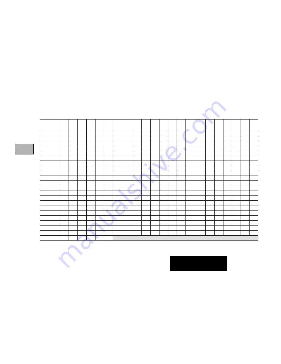
background image

Switch Settings

4-13

Classic PLC-5
processors only

Station

Number

1

2

3

4

5

6

Station

Number

1

2

3

4

5

6

Station

Number

1

2

3

4

5

6

0

on

on

on

on

on

on

26

on

off

off

on

off

on

53

off

off

on

off

on

off

1

off

on

on

on

on

on

27

off

off

off

on

off

on

54

on

on

off

off

on

off

2

on

off

on

on

on

on

30

on

on

on

off

off

on

55

off

on

off

off

on

off

3

off

off

on

on

on

on

31

off

on

on

off

off

on

56

on

off

off

off

on

off

4

on

on

off

on

on

on

32

on

off

on

off

off

on

57

off

off

off

off

on

off

5

off

on

off

on

on

on

33

off

off

on

off

off

on

60

on

on

on

on

off

off

6

on

off

off

on

on

on

34

on

on

off

off

off

on

61

off

on

on

on

off

off

7

off

off

off

on

on

on

35

off

on

off

off

off

on

62

on

off

on

on

off

off

10

on

on

on

off

on

on

36

on

off

off

off

off

on

63

off

off

on

on

off

off

11

off

on

on

off

on

on

37

off

off

off

off

off

on

64

on

on

off

on

off

off

12

on

off

on

off

on

on

40

on

on

on

on

on

off

65

off

on

off

on

off

off

13

off

off

on

off

on

on

41

off

on

on

on

on

off

66

on

off

off

on

off

off

14

on

on

off

off

on

on

42

on

off

on

on

on

off

67

off

off

off

on

off

off

15

off

on

off

off

on

on

43

off

off

on

on

on

off

70

on

on

on

off

off

off

16

on

off

off

off

on

on

44

on

on

off

on

on

off

71

off

on

on

off

off

off

17

off

off

off

off

on

on

45

off

on

off

on

on

off

72

on

off

on

off

off

off

20

on

on

on

on

off

on

46

on

off

off

on

on

off

73

off

off

on

off

off

off

21

off

on

on

on

off

on

47

off

off

off

on

on

off

74

on

on

off

off

off

off

22

on

off

on

on

off

on

50

on

on

on

off

on

off

75

off

on

off

off

off

off

23

off

off

on

on

off

on

51

off

on

on

off

on

off

76

on

off

off

off

off

off

24

on

on

off

on

off

on

52

on

off

on

off

on

off

77

off

off

off

off

off

off

25

off

on

off

on

off

on

on = closed
off = open

Summary of Contents for 1785

Page 1: ...2 Conversion 3 24 Bit Modify and Move 3 26 File 3 28 Diagnostic 3 30 Shift Register 3 32 Sequencer 3 35 Program Control 3 36 Processor Control and Message 3 41 Block and ControlNet Transfer 3 43 ASCII 3 47 Chassis Backplane 4 1 Chassis Configuration 4 3 Complementary I O 4 4 Enhanced and Ethernet PLC 5 4 7 ControlNetwork Address 4 11 Classic PLC 5 4 12 Ethernet Jumper 4 21 Enhanced and Ethernet PL...

Page 2: ...ation Because of the variety of uses for the products described in this publication those responsible for the application and use of this control equipment must satisfy themselves that all necessary steps have been taken to assure that each application and use meets all performance and safety requirements including any applicable laws regulations codes and standards The illustrations charts sample...

Page 3: ...ny Inc is prohibited Summary of Changes In this release of the PLC 5 Quick Reference we have altered the way we reference software documentation Rather than show specific screens and key sequences which may vary according to the software package you are using we refer you instead to the programming software documentation that accompanies your particular software package Of course we still provide ...

Page 4: ...5 12 PLC 5 15 PLC 5 20 PLC 5 25 PLC 5 30 PLC 5 40 PLC 5 40L PLC 5 60 PLC 5 60L PLC 5 80 PLC 5 20E PLC 5 40E PLC 5 80E PLC 5 250 PLC 5 20C PLC 5 40C PLC 5 80C Ethernet and DH are trademarks of Rockwell Automation This name Represents these processors Enhanced PLC 5 11 PLC 5 40 PLC 5 20 PLC 5 60 PLC 5 30 PLC5 80 PLC 5 40L PLC 5 60L Ethernet PLC 5 20E PLC 5 40E PLC5 80E ControlNet Phase 1 5 PLC 5 20C...

Page 5: ...en red Connect programming terminal here when channel 1A is configured for DH communications Channel 1A communication port Install memory module here Battery holder Channel 1B status indicator green red Channel 1B communication port PLC 5 11 Processor PLC 5 20 Processor Battery red Processor RUN FAULT green red Force amber Channel 0 communication status green Indicators ...

Page 6: ...communication port Channel 2 status indicator green red Channel 2 extended local I O communication port Channel 2B status indicator green red Install memory module here Channel 1B status indicator green red Channel 0 on board serial port The PLC 5 30 processor has 2 communication ports and 1 serial port Battery red Processor RUN FAULT green red Force amber Communication ACTIVE FAULT status green r...

Page 7: ...us indicator green red Channel 1B Channel 2 Ethernet status indicators Channel 2 Indicators Battery red Force amber Communication ACTIVE FAULT green red Channel 0 on board serial port Labels to write information about the channel communication mode station addresses etc Keyswitch Channel 1A Channel 1B Battery holder Channel 2 Indicators PLC 5 40E 5 80E Processor Channel 1A status indicator green r...

Page 8: ...Space Battery Holder Channel 1B Keyswitch I O Status Indicator Channel 2 Status Indicators Network Access Port Channel 2 Channel 1 Status Indicators DH Programming Terminal Connection to Channel 1A Channel 1A Channel 1B Battery Processor RUN FAULT Force Channel 0 Communication ACTIVE FAULT Channel 0 on board serial port Memory Module Space Battery Holder PLC 5 40C15 5 80C15 Processor Front Panel C...

Page 9: ...cessor Keyswitch DH communication indicator ACTIVE FAULT green red Connect programming terminal here Connect DH link here Adapter indicator green Connect remote I O link here Battery holder Write the DH network station number on this label 12373 Battery red Processor RUN FAULT green red Force amber Indicators Front Panel Classic PLC 5 Processors ...

Page 10: ...utputs using 16 or 32 pt modules 2 adapter remote I O scanner DH link PLC 5 25 13K expands to 21K 1 resident 28 7 I O racks 1024 1 1024 inputs and 1024 outputs using 16 or 32 pt modules 2 adapter remote I O scanner DH link PLC 5 11 8K 1 resident 4 1 I O rack rack must be addressed as rack 3 256 8 pt 384 16 pt or 512 16 pt 1 512 16 pt or 768 32 pt 2 1 channel remote I O scanner adapter DH link 1 RS...

Page 11: ... I O racks 512 1 512 inputs and 512 outputs using 16 or 32 pt modules 1 channel remote I O scanner adapter DH link 1 channel DH link 1 RS 232 RS 422 RS 423 serial port 1 channel Ethernet PLC 5 20C15 16K 1 resident 12 3 I O racks 512 1 512 inputs and 512 outputs using 16 or 32 pt modules 1 channel remote I O scanner adapter DH link 1 channel DH link 1 RS 232 RS 422 RS 423 serial port ControlNet PLC...

Page 12: ...local I O scanner PLC 5 40E 48K3 1 resident 16 rack addressing capability 60 15 I O racks 2048 1 2048 inputs and 2048 outputs using 16 or 32 pt modules 2 channels remote I O scanner adapter DH link 1 RS 232 RS 422 RS 423 serial port 1 channel Ethernet PLC 5 40C15 48K3 1 resident 60 15 I O racks 2048 1 2048 inputs and 2048 outputs using 16 or 32 pt modules 2 channels remote I O scanner adapter DH l...

Page 13: ...utputs using 16 or 32 pt modules 2 channels remote I O scanner adapter DH link 1 RS 232 RS 422 RS 423 serial port 1 channel Ethernet PLC 5 80C15 3 4 100K 1 resident 92 2 23 I O racks 3072 1 3072 inputs and 3072 outputs using 16 or 32 pt modules 2 channels remote I O scanner adapter DH link 1 RS 232 RS 422 RS 423 serial port 1 channel ControlNet 1 Any mix of I O 2 Maximum of 32 physical devices cha...

Page 14: ... 19 Rack Power Supply Socket 1771 A1B 4 slot X left 1771 A2B 8 slot X left 1771 A3B 12 slot X X top 1771 A3B1 12 slot X left 1771 A4B 16 slot X left When using these processors with the 1771 A1 A2 and A4 chassis Only this mode of addressing is supported Classic PLC 5 processors 2 slot and 1 slot in the local rack Enhanced and Ethernet PLC 5 processors 2 slot addressing ControlNet PLC 5 processors ...

Page 15: ...lot 1771 P4 120V ac 8 11 16 16 slot 1771 P4S 120V ac 8 11 16 16 slot 1771 P4S1 100V ac 8 16 slot 1771 P4R 120V ac 8 16 24 2 slot 1771 P5 24V dc 8 16 slot 1771 P6S 220V ac 8 16 slot 1771 P6S1 200V ac 8 16 slot 1771 P6R 220V ac 8 16 24 2 slot 1771 P7 120 220V ac 16 external 1 1771 PS7 120 220V ac 16 external 1 1 You cannot use an external power supply and a power supply module to power the same chas...

Page 16: ... 16 16 slot 1771 P4S1 100V ac 8 16 slot 1771 P4R 120V ac 8 16 24 2 slot 1771 P5 24V dc 8 16 slot 1771 P6S 220V ac 8 16 slot 1771 P6S1 200V ac 8 16 slot 1771 P6R 220V ac 8 16 24 2 slot 1771 P1 120 220V ac 6 5 external 1 1771 P2 120 220V ac 6 5 external 1 1771 P7 120 220V ac 16 external 1 1771 PS7 120 220V ac 16 external 1 1777 P2 120 220V ac 9 external 1 1777 P4 24V dc 9 external 1 1 You cannot use...

Page 17: ...Create or delete ladder files SFC files data table files X X Edit online ladder files and SFC files program files already exist X X X Force live outputs X X Prohibit processor from scanning program X X Change operating mode using a programming device X X Download to from EEPROM X X Automatically configure remote I O X X Edit data table values data table files already exist X X X X Establish Contro...

Page 18: ...r in RUN mode 2 processor in TEST mode 3 processor in PROG mode 4 processor burning EEPROM 5 processor in download mode 6 processor has test edits enabled 7 mode select switch in REMOTE position 8 forces enabled 9 forces present 10 processor successfully burned EEPROM 11 performing online programming 12 not defined 13 user program checksum calculated 14 last scan of ladder or SFC step 15 processor...

Page 19: ...Last program scan in ms S 9 Maximum program scan in ms S 2 Switch setting information bits 0 6 DH station number bit 11 12 are set based on the I O chassis backplane switches bit 12 bit 11 I O chassis addressing 0 0 illegal 1 0 1 2 slot 0 1 1 slot 1 1 2 slot bit 13 1 load from EEPROM bit 14 1 RAM backup not configured bit 15 1 memory unprotected S 3 to S 6 Active Node table for channel 1A Word Bit...

Page 20: ...memory transfer at power up 4 edits prevent SFC continuing data table size changed during program mode reset automatically in run mode 5 invalid I O status file 6 not defined 7 no more command blocks exist 8 not enough memory on the memory module to upload the program from the processor 9 no MCP is configured to run 10 MCP not allowed 11 PII word number not in local rack 12 PII overlap 13 no comma...

Page 21: ...ling program code 70 duplicate LBLs found 5 start up protection fault processor sets this bit when powering up in run mode if bit S 26 1 is set 6 peripheral device fault 7 jumped to fault routine codes 0 9 8 watchdog faulted 9 system configured wrong codes 80 89 10 recoverable hardware error 11 MCP does not exist or is not ladder or SFC file 12 PII does not exist or is not ladder 13 STI does not e...

Page 22: ...oo many operands for instruction 16 bad instruction found 17 no expression end in a CPT math expression 18 missing end of edit zone 19 download aborted 20 indirect address out of range high 21 indirect address out of range low 22 attempt to access undefined file 23 file number less than 0 or greater than number of defined files or indirect reference to file 0 1 2 or bad file number24 indirect refe...

Page 23: ... timer parameters entered 35 bad PID delta time entered 36 PID setpoint out of range 37 invalid I O specified in an immediate I O instruction 38 invalid use of return instruction 39 FOR loop missing NXT 40 control file too small 41 NXT instruction with no FOR 42 jump target does not exist or JMP missing LBL 43 file is not an SFC 44 error using SFR 45 invalid channel number entered 46 IDI or IDO in...

Page 24: ...ps back to itself 77 SFC references a step transition subchart or SC file that is missing empty or too small 78 SFC could not continue after power loss 79 error in downloading an SFC to a processor that cannot run SFCs or this specific PLC processor does not support this Enhanced SFC 80 I O configuration error 81 illegal setting of I O chassis backplane switch 82 illegal cartridge type 83 user wat...

Page 25: ... a hardware failure 96 Sidecar module not physically connected to the PLC 5 processor 97 Sidecar module requested a pool size that is too small for PCCC command occurs at power up 98 Sidecar module first last 16 bytes RAM test failed 99 Sidecar module to processor data transfer faulted 100 Processor to sidecar module data transfer failed 101 Sidecar module end of scan data transfer failed 102 The ...

Page 26: ...26 5 46 and 5 86 processors only 200 ControlNet scheduled output data missed 201 ControlNet input data missed 202 Not used 203 Reserved 204 ControlNet configuration is too complex 205 ControlNet configuration exceeds bandwidth 206 Reserved 207 Reserved 208 Too many pending ControlNet I O connections S 13 Program file where fault occurred S 14 Rung number where fault occurred S 15 VME status file S...

Page 27: ...mote I O rack in local rack table or remote I O rack is greater than the image size 7 firmware revision for channel pairs 1A 1B or 2A 2B does not match processor firmware revision 8 ASCII instruction error 9 duplicate node address 10 DF1 master poll list error 11 protected processor data table element violation 12 protected processor file violation 13 using all 32 ControlNet MSGs 14 using all 32 C...

Page 28: ...k when reset local rack address is 0 When set local rack address is 1 3 Set complementary I O when reset complementary I O is not enabled When set complementary I O is enabled 4 Local block transfer compatibility bit when reset normal operation When set eliminates frequent checksum errors to certain BT modules 5 PLC 3 scanner compatibility bit when set 1 adapter channel response delayed by 1 ms wh...

Page 29: ...33 S 34 and S 35 S 33 Rack control bits S 33 0 7 I O rack inhibit bits for racks 10 17 octal S 33 8 15 I O rack reset bits for racks 10 17 See also S 7 S 27 S 32 S 34 and S 35 S 34 Global status bits S 34 0 7 rack fault bits for racks 20 27 octal S 34 8 15 rack queue full bits for racks 20 27 See also S 7 S 27 S 32 S 33 and S 35 S 35 Rack control bits S 35 0 7 I O rack inhibit bits for racks 20 27...

Page 30: ... ControlNet processors S 38 S 45 Reserved S 46 PII program file number S 47 PII module group S 48 PII bit mask S 49 PII compare value S 50 PII down count S 51 PII changed bit S 52 PII events since last interrupt S 53 STI scan time in ms S 54 STI maximum scan time in ms S 55 PII last scan time in ms S 56 PII maximum scan time in ms S 57 User program checksum S 58 Reserved S 59 Extended local I O ch...

Page 31: ...and blocks being used by channel pair 1A 1B S 65 The number of remote block transfer command blocks being used by channel 2A 2B or by channel 2 ControlNet S 66 Reserved S 72 ControlNet node of this processor S 73 ControlNet PLC 2 compatibility file S 74 Time in msec between itemations of ControlNet subsystem diagnostics S 75 Maximum of S 74 S 76 Number of slots in processor resident local chassis ...

Page 32: ...for MCP A Bit 1 for MCP B etc S 80 S 127 MCP file number MCP scan time in ms MCP max scan time in ms The above sequence applies to each MCP therefore each MCP has 3 status words For example word 80 file number for MCP A word 81 scan time for MCP A word 82 maximum scan time for MCP A word 83 file number for MCP B word 84 scan time for MCP B etc ...

Page 33: ...d I O status file N15 0 N15 1 N15 14 N15 15 rack 0 rack 7 maximum for PLC 5 25 5 30 processors Word in integer file N15 30 N15 31 rack 17 maximum for PLC 5 40 5 40L 5 40E 5 40C processors N15 46 N15 47 rack 27 maximum for PLC 5 60 5 60L 5 80 5 80E 5 80C processors rack 3 maximum for PLC 5 11 5 15 5 20 5 20E and 5 20C processors ...

Page 34: ...starting I O group 2 02 third 1 4 rack starting I O group 4 03 fourth1 4 rack starting I O group 6 Present bits 08 first 1 4 rack starting I O group 0 09 second 1 4 rack starting I O group 2 10 third 1 4 rack starting I O group 4 11 fourth1 4 rack starting I O group 6 00 01 02 03 04 05 06 07 08 09 10 11 12 13 14 15 Not Used Not Used Fault Bits Present Bits N15 14 ...

Page 35: ...p 0 09 second 1 4 rack starting I O group 2 10 third 1 4 rack starting I O group 4 11 fourth1 4 rack starting I O group 6 ATTENTION When you use a ladder program or the software to inhibit and reset an I O rack you must set or cleartheresetandinhibitbitsthatcorrespondtoeachquarterrackinagivenchassis Failuretosetalltheappropriate bits could cause unpredictable operation due to scanning only part of...

Page 36: ......

Page 37: ...ords 2000 structures 6 3 structure Control R 6a 6000 words 2000 structures 6 3 structure Integer N 7a 2000 words 6 1 word Floating point F 8a 4000 words 2000 structures 6 2 structure ASCII A 3 999 2000 words 6 1 2 per character BCD D 3 999 2000words 6 1 word Block transfer BT 3 999 12000 words 2000 structures 6 6 structure CIO CT 3 999 12000 words 2000 structures 6 6 structure Message MG 3 999 327...

Page 38: ...0 structures 6 3 structure Integer N 71 1000 words 6 1 word Floating point F 81 2000 words 1000 structures 6 2 structure ASCII A 3 999 1000 words 6 1 2 per character BCD D 3 999 1000words 6 1 word Block transfer BT 3 999 6000 words 1000 structures 6 6 structure Message MG 3 999 32760 words 585 structuresb 6 56 structure PID PD 3 999 32718 words 399 structures2 6 82 structure SFC status SC 3 999 30...

Page 39: ...2 file 1 word Bit binary B 3 999 3 1000 words 2 file 1 word Timer T 3 999 4 3000 words 1000 structures 2 file 3 structure Counter C 3 999 5 3000 words 1000 structures 2 file 3 structure Control R 3 999 6 3000 words 1000 structures 2 file 3 structure Integer N 3 999 7 1000 words 2 file 1 word Floating Point F 3 999 8 1000 words 2 file 2 structure ASCII A 3 999 1000 words 2 file 1 2 per character BC...

Page 40: ...999 2 1999 2 Structured Text1 2 1999 2 Assigned as needed Subroutines Fault Routines Selectable Timed Interrupts Processor Input Interrupts 1 SFC Step Transition SFC Actions 1 3 999 2 1999 1 Enhanced Ethernet and ControlNet PLC 5 processors only 2 Enhanced Ethernet and ControlNet PLC 5 processors can have up to 16 main control programs in any combination of SFC ladder and structured text PLC 5 Mem...

Page 41: ... 03 octal PLC 5 10 5 11 5 12 5 15 5 20 5 20E 5 20C15 00 07 octal PLC 5 25 5 30 00 17 octal PLC 5 40 5 40L 5 40E 5 40C15 00 27 octal PLC 5 60 5 60L 5 80 5 80E 5 80C15 c I O group number 0 7 octal dd terminal bit number 00 17 octal Examples I 001 07 input device rack 00 group 1 terminal bit 7 O 074 10 output device rack 07 group 4 terminal bit 10 ...

Page 42: ...t output files 0 31 decimal for the status file Classic PLC 5 processors up to 0 127 decimal for the status file 0 999 for all the file types except MG PD and ST files Period delimiter is used only with structure member mnemonics in counter timer and control files s Structure member mnemonic is used only with timer counter control BT MG PD SC and ST files Bit delimiter separates bit number b Bit n...

Page 43: ...Place the character immediately before the file type identifier in a logical address Important File instructions manipulate the offset value stored at S 24 Make sure that you monitor or load the offset value you want prior to using an indexed address Unpredictable machine operation could occur Indirect Addressing You can indirectly address the following file number element number bit number Substi...

Page 44: ...ut image table I O 2 slot addressing 1 slot addressing 1 2 slot addressing 8 pt modules no restriction on module placement no restriction on module placement but does not make best use of I O image and available I O addresses no restriction on module placement but does not make best use of I O image and available I O addresses 16 pt modules must use 1 input and 1 output module per even odd slot pa...

Page 45: ...U DN EM LEN POS BSL BSR EN DN ER UL LEN POS FBC DDT EN DN ER IN FD LEN POS SQI SQO SQL EN DN ER LEN POS ASCII R6 n 2 ARL 1 AWT 1 AWA 1 EN EU DN EM ER UL LEN POS AHL 1 EN DN EM ER FD ACB 1 ABL 1 EN EU DN EM ER FD COMPUTE R6 n 2 AVE 1 SRT 1 STD 1 EN DN ER LEN POS 1 Enhanced Ethernet and ControlNet PLC 5 processors only 2 n starting structure number 0 999 Status Bits EN enable TT timing DN done OV ov...

Page 46: ...ruction on the same rung go true set 1 bit O 013 01 which corresponds to terminal 1 of an output module in I O rack 1 I O group 3 Output Latch OTL If the input conditions preceding this output instruction on the same rung go true set 1 bit O 013 01 which corresponds to terminal 1 of an output module in I O rack 1 I O group 3 This data table bit remains set until an OTU instruction resets the bit O...

Page 47: ... program scan is interrupted only to update the input image with the latest states as found in the remote I O or ControlNet buffer Immediate Output IOT This instruction updates a word of output image bits before the next normal output image update For a local chassis program scan is interrupted while the outputs of the addressed I O group are scanned for a remote or ControlNet chassis program scan...

Page 48: ...integrity in the case of Selectable Timed Interrupts STIs Immediate Data Output IDO for ControlNet processors only If the input conditions are true an immediate data output is initiated that updates the private ControlNet output buffers from the source file before the next normal output image update The Data file offset 175 is the offset into the buffer where the data is stored The Length 24 ident...

Page 49: ...he input conditions are false timer T4 1 starts incrementing in 10 ms intervals as long as the rung remains false When the accumulated value is greater than or equal to the preset value 180 the timer stops and resets the timer done bit TIMER ON DELAY Timer T4 1 Time Base 1 0 Preset 15 Accum 0 TON Rung Condition EN 15 TT 14 DN 13 ACC Value TON Status False 0 0 0 0 Reset True 1 1 0 increase Timing T...

Page 50: ...r continues When the accumulated value is greater than or equal to the preset 10 the timer stops and sets the timer done bit Timer Reset RES If the input conditions go true timer T4 1 is reset This instruction resets timers and counters as well as control blocks This is necessary to reset the RTO accumulated value RETENTIVE TIMER ON Timer T4 10 Time Base 1 0 Preset 10 Accum 0 RTO Rung Condition EN...

Page 51: ...er C5 1 starts counting incrementing by 1 every time the rung goes from false to true When the accumulated value is greater than or equal to the preset value 10 the counter sets the counter done bit COUNT UP Counter C5 1 Preset 10 Accum 0 CTU Rung Condition CU 15 DN 13 OV 12 ACC Value CTU Status False 0 0 0 0 Reset Toggle True 1 0 0 incr by 1 Counting True 1 1 0 preset Done True 1 1 1 32767 Overfl...

Page 52: ... When the accumulated value is less than or equal to the preset value 10 the counter resets the counter done bit Counter Reset RES If the input conditions go true counter C5 1 is reset This instruction resets timers and counters as well as control blocks COUNT DOWN Counter C5 1 Preset 10 Accum 35 CTD Rung Condition CD 14 DN 13 UN 11 ACC Value CTD Status False 0 0 0 0 Reset False 0 1 0 preset Prelo...

Page 53: ...an greater than or equal not equal Complex expressions up to 80 characters are valid with Enhanced and ControlNet PLC 5 processors only Limit Test LIM If the Test value N7 15 is the Low Limit N7 10 and the High Limit N7 20 this instruction is true COMPARE Expression N7 5 N7 10 CMP LIMIT TEST CIRC Low limit N7 10 3 Test N7 15 4 High limit N7 20 22 LIM Low Limit Test High Limit LIM 0 0 10 T 5 5 10 T...

Page 54: ...e D9 5 and passes that value through the Mask D9 6 Then the processor compares the result to the Compare value D9 10 If the result and this comparison values are equal the instruction is true MASKED EQUAL Source D9 5 0000 Mask D9 6 0000 Compare D9 10 0000 MEQ Source Mask Compare MEQ 0008 0008 0009 F 0008 0001 0001 F 0087 000F 0007 T 0087 00F0 0007 F ...

Page 55: ... value in Source B N7 10 this instruction is true Less than or Equal LEQ If the value in Source A N7 5 is or to the value in Source B N7 10 this instruction is true Less than LES If the value in Source A N7 5 is the value in Source B N7 10 this instruction is true Not Equal NEQ If the value in Source A N7 5 is not equal to the value in Source B N7 10 this instruction is true xxxxxxxxxxxxx Source A...

Page 56: ...l log LN sine SIN cosine COS tangent TAN inverse sine ASN inverse cosine ACS inverse tangent ATN Complex expressions up to 80 characters are valid with Enhanced and ControlNet PLC 5 processors only Arc Cosine ACS Enhanced Ethernet and ControlNet PLC 5 processors only When the input conditions are true take the arc cosine of the Source F8 19 and store the result in the Destination F8 20 The Source ...

Page 57: ...the Destination F8 18 The Source is interpreted as radians and must be greater than or equal to 1 and less than or equal to 1 ADD Source A N7 3 3 Source B N7 4 1 Dest N7 12 4 ADD Status Bit Description C sets if carry is generated otherwise resets V sets if overflow is generated otherwise resets Z sets if the result is zero otherwise resets S sets if the result is negative otherwise resets ARCSINE...

Page 58: ... When the input conditions go from false to true add N7 1 N7 2 N7 3 and N7 4 Divide the sum by 4 and store the result in N7 0 ARCTANGENT Source F8 21 0 7853982 Destination F8 22 0 6657737 ATN Status Bit Description C always resets V sets if overflow is generated otherwise resets Z sets if the result is zero otherwise resets S sets if the result is negative otherwise resets AVERAGE FILE File N7 1 D...

Page 59: ...take the cosine of the Source F8 13 and store the result in the Destination F8 14 The Source is interpreted as radians CLR Dest D9 34 0000 CLR Status Bit Description C always reset V always reset Z always set S always reset COSINE Source F8 13 0 7853982 Destination F8 14 0 7071068 COS Status Bit Description C always resets V sets if overflow is generated otherwise resets Z sets if the result is ze...

Page 60: ...e N7 0 and store the result in the Destination F8 20 The Source must be positive greater than 0 DIVIDE Source A N7 3 3 Source B N7 4 1 Dest N7 12 3 DIV Status Bit Description C always resets V sets if division by zero or overflow otherwise resets Z sets if the result is zero otherwise resets S sets if the result is negative otherwise resets NATURAL LOG Source N7 0 5 Destination F8 20 1 609438 LN S...

Page 61: ... the value in Source A N7 3 by the value in Source B N7 4 store the result in the Destination N7 12 LOG BASE 10 Source N7 2 5 Destination F8 3 0 6989700 LOG Status Bit Description C always resets V sets if overflow is generated otherwise resets Z sets if the result is zero otherwise resets S sets if the result is negative otherwise resets MULTIPLY Source A N7 3 3 Source B N7 4 1 Dest N7 12 3 MUL S...

Page 62: ...he sine of the Source F8 11 and store the result in the Destination F8 12 The Source is interpreted as radians NEGATE Source N7 3 3 Destination N7 12 3 NEG Status Bit Description C sets if the operation generates a carry otherwise resets V sets if overflow is generated otherwise resets Z sets if the result is zero otherwise resets S sets if the result is negative otherwise resets SINE Source F8 11...

Page 63: ...rocessors only Status Bits EN Enable DN Done Bit ER Error Bit When the input conditions go from false to true the elements in N7 1 N7 2 N7 3 and N7 4 are sorted into ascending order SQUARE ROOT Source N7 3 25 Destination N7 12 5 SQR Status Bit Description C always resets V sets if overflow occurs during floating point to integer conversion otherwise resets Z sets if the result is zero otherwise re...

Page 64: ...itions are true subtract the value in Source B N7 4 from the value in Source A N7 3 and store the result in the Destination N7 12 STANDARD DEVIATION File N7 1 Dest N7 0 Control R6 0 Length 4 Position 0 STD Status Bit Description C always resets V sets if overflow is generated otherwise resets Z sets if the result is zero otherwise resets S sets if the result is negative otherwise resets SUBTRACT S...

Page 65: ... 15 and store the result in the Destination F8 16 The Source must be greater than or equal to 102943 7 and less than or equal to 102943 7 The Source is interpreted as radians TANGENT Source F8 15 0 7853982 Destination F8 16 1 0000000 TAN Status Bit Description C always resets V sets if overflow is generated otherwise resets Z sets if the result is zero otherwise resets S sets if the result is nega...

Page 66: ...When the input conditions are true the processor performs a NOT takes the opposite of operation bit by bit on the Source D9 3 and stores the result in the Destination D9 5 The truth table for a NOT operation is Source Destination 0 1 1 0 BITWISE AND Source A D9 3 3F37 Source B D9 4 00FF Dest D9 5 0037 AND NOT Source A D9 3 00FF Destination D9 5 FF00 NOT Status Bit Description C always resets V alw...

Page 67: ...re true the processor evaluates an exclusive OR operation bit by bit between Source A D9 3 and Source B D9 4 and stores the result in the Destination D9 5 The truth table for an XOR operation is Source A Source B Result 0 0 0 1 0 1 0 1 1 1 1 0 BITWISE INCLUS OR Source A D9 3 3F37 Source B D9 4 00FF Dest D9 5 3FFF OR BITWISE EXCLUS OR Source A D9 3 3F37 Source B D9 4 3F37 Dest D9 5 0000 XOR Status ...

Page 68: ...re true convert the value in Source N7 3 to a BCD format and store the result in the Destination D9 5 FROM BCD Source D9 3 0037 Destination N7 12 37 FRD Status Bit Description C always resets V always resets Z sets if the destination value is zero otherwise resets S always resets TO BCD Source N7 3 44 Destination D9 5 0044 TOD Status Bit Description C always resets V sets if the source value is ne...

Page 69: ...ue in Source A to radians and stores the result in the Destination Source times π 180 RADIANS TO DEGREE Source F8 7 0 7853982 Destination F8 8 45 DEG Status Bit Description C always resets V sets if overflow is generated otherwise resets Z sets if the result is zero otherwise resets S sets if the result is negative otherwise resets DEGREES TO RADIAN Source N7 9 45 Destination F8 10 0 7853982 RAD S...

Page 70: ...ion bit 10 Move MOV When the input conditions are true move a copy of the value in Source N7 3 to the Destination N7 12 This overwrites the original value in the Destination BIT FIELD DISTRIB Source N7 3 0 Source bit 3 Dest N7 4 0 Dest bit 10 Length 6 BTD MOVE Source N7 3 0 Destination N7 12 0 MOV Status Bit Description C always resets V sets if overflow is generated during floating point to integ...

Page 71: ...s the value in the Source D9 3 through the Mask D9 5 and stores the result in the Destination D9 12 This overwrites the original value in the Destination MASKED MOVE Source D9 3 478F Mask D9 5 00FF Dest bit D9 12 Length 008F MVM Status Bit Description C always resets V always resets Z sets if the result is zero otherwise resets S sets if the result is negative otherwise resets ...

Page 72: ...scan one element in the files INC per scan or a specific number of elements NUM per scan The FAL instruction can perform these operations add subtract multiply divide convert from BCD FRD convert to BCD TOD square root SQR logical and AND logical or OR logical not NOT exclusive or XOR negate clear 0 move and the new math instructions see the CPT list File Fill FLL When the input conditions are tru...

Page 73: ... 0 controls the operation When the corresponding source elements are not equal element B4 4 and B5 4 in this example the processor stops the search and sets the found FD and inhibit IN bits so your ladder program can take appropriate action To continue the search comparison you must reset the IN bit To see a list of the available comparisons see the comparisons listed under the CMP instruction Fil...

Page 74: ...8 of the Source file I 031 with the bits in the Reference file B3 1 The processor stores the results mismatched bit numbers in the Result file N7 0 File R6 4 controls the compare and file R6 5 controls the file that contains the results The file containing the results can hold up to 10 the number specified in the Length field mismatches between the compared files FILE BIT COMPARE Source I 031 Refe...

Page 75: ... to the reference file for the next comparison The difference between the DDT and FBC instruction is that each time the DDT instruction finds a mismatch the processor changes the reference bit to match the source bit You can use the DDT instruction to update your reference file to reflect changing machine or process conditions Data Transition DTR The DTR instruction compares the bits in the Source...

Page 76: ...fifth bit B3 1 4 B3 20 is shifted into the UL bit of the control structure R6 53 Bit Shift Right BSR Status Bits EN Enable DN Done Bit ER Error Bit UL Unload Bit If the input conditions go from false to true the BSR instruction shifts the number of bits specified by Length 3 in File B3 starting with B3 2 0 B3 32 to the right by one bit position The source bit I 023 06 shifts into the third bit pos...

Page 77: ...ther element When the FIFO file stack is full 64 words loaded the DN bit is set FIFO Unload FFU Status Bits EU Enable Unload DN Done Bit EM Empty Bit When the input conditions go from false to true the processor unloads an element from N60 3 into N60 2 Each time the rung goes from false to true the processor unloads another element All the data in file N60 3 is shifted one position toward N60 3 Wh...

Page 78: ...oads another element When the LIFO file stack is full 64 words have been loaded the DN bit is set LIFO Unload LFU Enhanced Ethernet and ControlNet PLC 5 processors only Status Bits EN Enable Load EU Enable Unload DN Done Bit EM Empty Bit When the input conditions go from false to true the processor unloads the last element from N70 3 and puts it into N70 2 Each time the rung goes from false to tru...

Page 79: ...ied by Length 5 of the Source I 002 starting at the Position 0 The operation is controlled by the information in the control file R6 22 When the rung goes from false to true the SQL instruction increments the next step in the sequencer file and loads the data into it for every scan that the rung remains true Sequencer Output SQO Status Bits EN Enable DN Done Bit ER Error Bit When the rung goes fro...

Page 80: ... skips rungs by jumping to the rung identified by the label 10 Label LBL When the processor reads a JMP instruction that corresponds to label 10 the processor jumps to the rung containing the label and starts executing Must be the first instruction on a rung FOR Loop FOR The processor executes the rungs between the FOR and the NXT instruction repeatedly in one program scan until it reaches the ter...

Page 81: ...loop Break BRK When the input conditions go true the BRK instruction aborts a For Next loop Jump to Subroutine JSR If the input conditions are true the processor starts running a subroutine Program File 90 The processor uses the Input Parameters N16 23 N16 24 231 in the subroutine and passes Return Parameters N19 11 N19 12 back to the main program where the processor encountered the JSR instructio...

Page 82: ...urn Parameters N43 3 N43 4 to be returned to the JSR instruction in the main program Temporary End TND The TND instruction stops the processor from scanning the rest of the program i e this instruction temporarily ends the program Always False AFI The AFI instruction disables the rung i e the rung is always false One Shot ONS If the input conditions preceding the ONS instructions on the same rung ...

Page 83: ...scan when the rung goes from true to false One Shot Rising OSR Enhanced Ethernet and ControlNet PLC 5 processors only Status Bits OB Output Bit 1 SB Storage Bit 1 The OSR instruction triggers an event to occur one time Use the OSR instruction whenever an event must start based on the change of state of a rung from false to true not on the resulting rung status The output bit N7 0 15 is set 1 for o...

Page 84: ... instruction goes false End of Transition EOT The EOT instruction should be the last instruction in a transition file If you do not use an EOT instruction the processor always evaluates the transition as true User Interrupt Disable UID Enhanced Ethernet and ControlNet PLC 5 processors only The UID instruction temporarily disables an interrupt driven ladder program such as an STI or PII from interr...

Page 85: ...ControlNet PLC 5 processors you can use the PD control block If you use PD control block then there is no done bit Also the rung input conditions only need to be true for these processors Message MSG If the input conditions are true the data is transferred according to the instruction parameters you set when you entered the message instruction The Control Block N7 10 contains status and instructio...

Page 86: ...Start Bit EN Enable Bit If the input conditions go from false to true the data is transferred according to the instruction parameters you set when you enter the message instruction The Control Block MG10 10 contains status and instruction parameters You cannot use N integer control blocks on the ControlNet network For continuous MSGs condition the rung to be true for only one scan SEND RECEIVE MES...

Page 87: ...word count 2 transmitted word count 3 file number 4 element number Block Transfer BT control block Word Mnemonic Description EN thru RW status bits RLEN requested length DLEN transmitted word length error code FILE file number ELEM element number RGS rack group slot Word 0 15 14 13 12 11 10 09 08 07 06 05 04 03 02 01 00 EN ST DN ER CO EW NR TO RW rack group slot ...

Page 88: ...60L 5 60C 5 80 5 40E 5 80E 5 80C processors PLC 5 60 5 80 5 80E 5 80C processors S 7 bit BT queue full for rack S 32 bit BT queue full for rack S 34 bit BT queue full for rack 081 0 08 10 08 20 091 1 09 11 09 21 101 2 10 12 10 22 111 3 11 13 11 23 12 4 12 14 12 24 13 5 13 15 13 25 14 6 14 16 14 26 15 7 15 17 15 27 1 PLC 5 10 5 11 5 12 5 15 5 20 5 20E 5 20C processors also ...

Page 89: ...5 processors you can use the BT control block Block Transfer Write BTW If the input conditions go from false to true the block transfer write is initiated for the I O module located at rack 1 group 0 module 0 The Control Block N10 0 5 word file contains status for the transfer The Data File contains the data to write to the module N10 10 The BT Length 40 identifies the number of words in the trans...

Page 90: ...EN Enable Bit If the input conditions go from false to true the data is transferred according to the instruction parameters you set when you enter the ControlNet I O transfer instruction The Control Block CT21 50 contains status and instruction parameters You cannot use N integer control blocks on the ControlNet network For continuous CIOs condition the rung to be true for only one scan CNET I O T...

Page 91: ...s in the buffer and puts this value into the position word POS of the control structure The processor also displays this value in the characters field of the display Convert ASCII String to Integer ACI Enhanced and Ethernet and ControlNet PLC 5 processors only If input conditions are true the processor converts the string in ST38 90 to an integer and stores the result in N7 123 En Enable DN Done B...

Page 92: ...nd ControlNet PLC 5 processors only If input conditions are true the processor extracts 10 characters starting at the 42nd character of ST38 40 and stores the result in ST52 75 Convert Integer to ASCII String AIC Enhanced Ethernet and ControlNet PLC 5 processors only If input conditions are true the processor converts the value 876 to a string and stores the result in ST38 42 STRING CONCATENATE So...

Page 93: ...if 0 BIt 0 and 1 of the OR mask cause the line s to set if 1 and leave the line s unchanged if 0 ASCII Read ARD Enhanced Ethernet and ControlNet PLC 5 processors only Status Bits EN Enable DN Done Bit ER Error Bit UL Unload EM Empty EU Queue If input conditions go from false to true read 50 characters from the buffer and move them to ST52 76 The number of characters read is stored in R6 32 POS and...

Page 94: ...s read is stored in R6 30 POS and displayed in the Characters Read Field of the instruction display ASCII String Search ASC Enhanced Ethernet and ControlNet PLC 5 processors only If input conditions are true search ST52 80 starting at the 35th character for the string found in ST38 40 In this example the string was found at index 42 If the string is not found the ASCII instruction minor fault bit ...

Page 95: ...lse ASCII Write Append AWA Enhanced Ethernet and ControlNet PLC 5 processors only Status Bits EN Enable DN Done Bit ER Error Bit UL Unload EM Empty EU Queue If input conditions go from false to true read 50 characters from ST52 76 and write it to channel 0 and append the two character configuration in the channel configuration default CR LF The number of characters sent is stored in R6 32 POS and ...

Page 96: ...us Bits EN Enable DN Done Bit ER Error Bit UL Unload EM Empty EU Queue If input conditions go from false to true write 40 characters from ST37 40 to channel 0 The number of characters sent is stored in R6 23 POS and displayed in the characters sent field of the instruction display ASCII WRITE Channel 0 Source ST37 40 Control R6 23 String Length 40 Characters Sent AWT ...

Page 97: ...mory transfers to processor memory at powerup 2 EEPROM memory transfers to processor memory if processor memory not valid EEPROM memory does not tranfer to processor memory 3 Processor memory protection disabled Processor memory protection enabled 4 1 Regardless of this switch setting outputs are reset when either of the following occurs l processor detects a runtime error l an I O chassis backpla...

Page 98: ...apter Processor can restart the I O chassis after a communication fault Set this switch to ON if you plan to use I O rack auto configuration You must manually restart the I O chassis with a switch wired to the 1771 AS or ASB or with the pushbutton mounted in the 1771 ALX ON ON ON ON ON OFF OFF OFF OFF OFF 2 slot 1 slot 1 1 2 slot 1 2 Not allowed 1 The 1771 AS adapter does not support 1 slot or 1 2...

Page 99: ...ug Settings N Y Y N Important You cannot power a single I O chassis with both a power supply module and an external power supply Set Y when you install a power supply module in the chassis Using Power Supply Module in the Chassis Y N Set N when you use an external power supply ...

Page 100: ...1 2 ON OFF OFF ON OFF OFF ON ON 57 6 Kbps 10 000 ft 3048m 115 2 Kbps 5 000 ft 1524m 230 4 Kbps 2 500 ft 762m not used I O Rack Number see next page First I O Group Number see below Link Response ON for series B emulation OFF for unrestricted Scan ON for all but last 4 slots OFF for all slots SW 1 SW 2 Max chassis distance on closed off open Pressed in at bottom Open OFF Pressed in at top Closed ON...

Page 101: ...n on on off off on 22 on off on on off on 07 on on on off off off 23 on off on on off off 10 on on off on on on 24 on off on off on on 11 on on off on on off 25 on off on off on off 12 on on off on off on 26 on off on off off on 13 on on off on off off 27 on off on off off off 14 on on off off on on PLC 5 15 5 20 5 20E 5 20C processors address racks 01 03 PLC 5 40 5 40E 5 40L 5 40C processors addr...

Page 102: ... 01 03 only Important Only seven racks can be complemented in a PLC 5 system ON Primary Chassis OFF Complementary Chassis 1 2 3 4 5 6 7 8 O N O F F 1 2 3 4 O N O F F 5 6 ON scans for all but last 4 slots OFF scans for all slots ON primary chassis OFF complementary chassis I O Rack Number First I O Group Number Link Response ON for series B emulation OFF for unrestricted SW 1 SW 2 Switch 1 2 ON OFF...

Page 103: ...itch Assembly SW1 Side view of PLC 5 30 5 40 5 40L 5 40C 5 60 5 60L 5 80 5 40E 5 80E 5 60C processors Switch Assembly SW1 1 2 3 4 5 6 7 1 2 3 4 5 6 7 Side View toggle pushed toward bottom on closed toggle pushed toward top off open Enhanced and ControlNet PLC 5 processors only To select Set switch To DH station number 1 through 6 see page 4 8 DH baud rate 7 on down 57 6kbps off up 230 4kbps ...

Page 104: ...D D D 35 U D U U U D 62 D U D D U U 10 D D D U D D 36 D U U U U D 63 U U D D U U 11 U D D U D D 37 U U U U U D 64 D D U D U U 12 D U D U D D 40 D D D D D U 65 U D U D U U 13 U U D U D D 41 U D D D D U 66 D U U D U U 14 D D U U D D 42 D U D D D U 67 U U U D U U 15 U D U U D D 43 U U D D D U 70 D D D U U U 16 D U U U D D 44 D D U D D U 71 U D D U U U 17 U U U U D D 45 U D U D D U 72 D U D U U U 20 D...

Page 105: ... 3 4 5 6 7 8 9 10 RS 232C D D D U U D D U D U RS 422 U U D U U U U U D U RS 423 D D D U U D U U D U Front of processor Front of processor Bottom view of PLC 5 11 5 20 5 20E 5 20C15 processors Switch Assembly SW2 Bottom view of PLC 5 30 5 40 5 40L 5 40C15 5 60 5 60L 5 80 5 40E 5 80E 5 80C15 processors Switch Assembly SW2 1 2 3 4 5 6 7 8 9 10 1 2 3 4 5 6 7 8 9 10 Side View toggle pushed down D on to...

Page 106: ...3 which is sufficient for most Ethernet networks If your Ethernet network conforms to the DIX standard set the jumper to ENET The hardware Ethernet address label is located to the right of the Ethernet configuration jumper This label shows the hardware Ethernet address assigned by Allen Bradley ENET 802 3 19915 Hardware Ethernet Address Label Ethernet Configuration Jumper Side View toggle pushed d...

Page 107: ...ry switches on the top of the processor You can select from as many as 99 network addresses from 01 to 99 for a processor on a ControlNet link 00 is invalid For optimum throughput assign addresses to your ControlNet nodes in a sequential order starting with 01 for the controlling processor 00 10 20 30 40 50 60 70 80 90 0 1 2 3 4 5 6 7 8 9 NET ADDRESS Network address 01 is shown ...

Page 108: ...ocessors Switch Assembly To select Set switch To DH station number 1 through 6 see page 5 12 Switch 7 not used 7 off scanner mode 8 off adapter 8 on 1 2 3 4 5 6 7 8 Top View of Module Switch Assembly SW1 Side View toggle pushed toward bottom on closed toggle pushed toward top off open ...

Page 109: ...on 63 off off on on off off 11 off on on off on on 37 off off off off off on 64 on on off on off off 12 on off on off on on 40 on on on on on off 65 off on off on off off 13 off off on off on on 41 off on on on on off 66 on off off on off off 14 on on off off on on 42 on off on on on off 67 off off off on off off 15 off on off off on on 43 off off on on on off 70 on on on off off off 16 on off off...

Page 110: ...ords to communicate with the adapter PLC 5 processor 2 off The host processor to use 4 words to communicate with the adapter PLC 5 processor 2 on The first I O group to be 0 3 on The first I O group to be 4 3 off To select the I O rack number of the adapter PLC 5 processor 4 through 8 see table below 1 2 3 4 5 6 7 8 1 2 3 4 Bottom View of Module Switch Assembly SW2 Side View toggle pushed toward b...

Page 111: ...o communicate with the adapter PLC 5 processor 2 off The host processor to use 4 words to communicate with the adapter PLC 5 processor 2 on The first I O group to be 0 3 on The first I O group to be 4 3 off To select the I O rack number of the adapter PLC 5 processor 4 through 8 see table below 1 2 3 4 5 6 7 8 1 2 3 4 Bottom View of Module Switch Assembly SW2 Side View toggle pushed toward bottom ...

Page 112: ... off on off 21 off on on on off 06 on on off off on 22 off on on off on 07 on on off off off 23 off on on off off 10 on off on on on 24 off on off on on 11 on off on on off 25 off on off on off 12 on off on off on 26 off on off off on 13 on off on off off 27 off on off off off 14 on off off on on PLC 5 15 5 20 5 20E 5 20C processors address racks 01 03PLC 5 40 5 40L 5 40E 5 40C processors address ...

Page 113: ...he host processor to use 8 words to communicate with the adapter PLC 5 2 off The host processor to use 4 words to communicate with the adapter PLC 5 2 on The first I O group to be 0 3 on The first I O group to be 4 3 off To select the I O rack number of the adapter PLC 5 processor 4 through 8 see below 1 2 3 4 5 6 7 8 1 2 3 4 Bottom View of Module Switch Assembly SW2 Side View toggle pushed toward...

Page 114: ... O Rack Number PLC 5 Processor as an Adapter in a PLC 2 20 PLC 2 30 or Sub I O Scanner Module System Rack 4 5 6 7 8 01 on on on on on 02 on on on on off 03 on on on off on 04 on on on off off 05 on on off on on 06 on on off on off 07 on on off off on on closed off open ...

Page 115: ... groups If You Want Set switch To Switch 1 is always unused 1 off The host processor to use 8 words to communicate with the adapter PLC 5 processor 2 off To select the I O rack number of the adapter PLC 5 processor 3 through 8 see below 1 2 3 4 5 6 7 8 1 2 3 4 Bottom View of Module Switch Assembly SW2 Side View toggle pushed toward bottom on closed toggle pushed toward top off open on closed off o...

Page 116: ...n on off on 10 on on off on on on 36 on off off off off on 63 off off on on off off 11 on on off on on off 37 on off off off off off 64 off off on off on on 12 on on off on off on 40 off on on on on on 65 off off on off on off 13 on on off on off off 41 off on on on on off 66 off off on off off on 14 on on off off on on 42 off on on on off on 67 off off on off off off 15 on on off off on off 43 of...

Page 117: ...o Switch 1 is always unused 1 off The host processor to use 4 words to communicate with the adapter PLC 5 processor 2 on The first I O group to be 0 3 on The first I O group to be 4 3 off To select the I O rack number of the adapter PLC 5 processor 4 through 8 see below 1 2 3 4 5 6 7 8 1 2 3 4 Bottom View of Module Switch Assembly SW2 Side View toggle pushed toward bottom on closed toggle pushed t...

Page 118: ...off on on off off 4 on on off on on 24 off on off on on 5 on on off on off 25 off on off on off 6 on on off off on 26 off on off off on 7 on on off off off 27 off on off off off 10 on off on on on 30 off off on on on 11 on off on on off 31 off off on on off 12 on off on off on 32 off off on off on 13 on off on off off 33 off off on off off 14 on off off on on 34 off off off on on 15 on off off on ...

Page 119: ...mote I O link 1 on Not an end device on the remote I O link 1 off An end device on the Data Highway Plus link 2 on Not an end device on the Data Highway Plus link 2 off Switch 3 is unused 3 off Switch 4 is unused 4 off 1 2 3 4 5 6 7 8 1 2 3 4 Switch Assembly SW3 Bottom View of Module Side View toggle pushed toward bottom on closed toggle pushed toward top off open on closed off open ...

Page 120: ......

Page 121: ...ROM normal operation none red blinking major fault run time error Check major fault bit in status file S 11 for error definition Clear fault bit correct problem and return to RUN mode red steady major fault user RAM has checksum error memory module error internal diagnostics have failed Clear memory and reload program Check backplane switch settings and or insert correct memory module Power down r...

Page 122: ...r FLASH memory checksum error Contact your local A B representative for a field firmware update COMM off no transmission on channel 0 normal operation if port is not being used none green blinking transmission on channel 0 normal operation if port being used none FORCE amber steady SFC and or I O forces enabled normal operation none amber blinking SFC and or I O forces present but not enabled norm...

Page 123: ...ion A or B green steady RIO scanner active RIO link all adapter modules are present and not faulted normal operation none RIO adapter communicating with scanner normal operation none DH processor is transmitting or receiving on DH link normal operation none green blinking rapidly or slowly RIO scanner at least one adapter is faulted or failed power off at remote rack cable broken Restore power to ...

Page 124: ...nner RIO adapter DH hardware fault hardware error Turn power off then on Check that the software configurations match the hardware set up Replace the processor red blinking rapidly or slowly RIO scanner faulted adapters detected cable disconnected or broken power off at remote racks Repair cable Restore power to racks DH bad communication on DH duplicate node detected Correct station address off R...

Page 125: ... I O scanner active extended local I O link all adapter modules are present and not faulted normal operation none green blinking rapidly or slowly extended local I O scanner at least one adapter is faulted or failed power off at extended local I O rack communication fault cable broken Restore power to the rack Restart adapters using the processor restart lockout push button Repair cable BATT PROC ...

Page 126: ...ware error Turn power off then on Check that the software configurations match the hardware set up Replace the processor red blinking rapidly or slowly extended local I O scanner all adapters faulted cable disconnected or broken terminator off power off at remote racks Repair cable Replace or repair terminator Restore power to racks off extended local I O scanner channel off line channel is not be...

Page 127: ...l hardware fault processor requires internal repair Contact your local Allen Bradley representative blinking red hardware or software fault detected and reported via a code fault code dependent Contact Global Technical Support GTS off Ethernet interface is functioning properly but it is not attached to an active Ethernet network normal operation Attach the processor to an active Ethernet network g...

Page 128: ...operation None Flashing Green Off At least one node configured for the ControlNet network not present or not operating properly Cable s or connector s broken or not connected Repair or replace cable s or connector s and reconnect Destination module s bad or missing Repair or replace module s Node s not on network Connect node to network Flashing Red Off All nodes configured for ControlNet not pres...

Page 129: ...ly Steady Red Faulted unit Cycle power or reset unit If fault persists contact your Rockwell Automation representative or distributor Flashing Green Normal operation if processor is in FLASH memory program mode No action required Flashing Red Green The processor s ControlNet address is above UMAX Configure the ControlNet network so that UMAX is at least as high as the processor s ControlNet addres...

Page 130: ...y tap Check media for broken cables loose connectors missing terminators etc No other nodes present on network Add other nodes to the network Flashing Red Green Incorrect network configuration Cycle power or reset unit If fault persists contact your Rockwell Automation representative or distributor 1 Definition of terms alternating the two indicators alternate between the two defined states at the...

Page 131: ...Then if necessary replace the processor FORCE amber steady forces enabled normal operation none amber blinking forces present but not enabled normal operation none off no forces present normal operation none BATT off battery is good normal operation none red steady battery low Replace battery within 1 2 days typical ADPT green steady processor is in adapter mode normal operation none off processor...

Page 132: ...sor memory being transferred to EEPROM normal operation none red blinking major fault run time error Check major fault bit in status file S 11 for error definition Clear fault bit correct problem and return to RUN mode red steady major fault user RAM has checksum error memory module error Clear memory and reload program Check backplane switch settings and or insert correct memory module off proces...

Page 133: ... Then if necessary replace the processor FORCE amber steady forces enabled normal operation none amber blinking forces present but not enabled normal operation none off no forces present normal operation none BATT off battery is good normal operation none red steady battery low Replace battery within 1 2 days typical ADPT green steady processor is in adapter mode normal operation none off processo...

Page 134: ...link normal operation none green blinking remote I O active and host processor is in program load or TEST mode normal operation none red steady no communication with host processor duplicate station address selected Correct station address green sporadic bad communication with host processor Check connections off no communication with host processor no action required COMM BATT FAULT REM I O PROC ...

Page 135: ...Series Software put the processor in PROG mode and do an auto configure for remote racks see your 6200 Series Software documentation green red blinking partial remote I O link fault one or more remote I O chassis faulted Check status bits in I O status file element 7 to identify faulted chassis number check wiring adapter module s power supplies If you have 6200 Series Software put the processor i...

Page 136: ...operation none red steady watchdog time out hardware error Turn power off then on Check that the software configurations match the hardware set up Replace the processor red sporadic bad communication on DH link duplicate station address selected Correct station address off if directly connected to processor no communication on DH link if last processor on DH link no communication on DH link no act...

Page 137: ...ule On Blink Off module placement error I O module in incorrect slot Place module in correct slot in chassis Blink in unison Off incorrect starting I O group number error in starting I O group number or I O rack address Check switch settings Refer to table 3 B to verify acceptable beginning I O group number set switches correctly On On On module not communicating incorrect baud rate setting Check ...

Page 138: ...quence on off from top to bottom module not communicating another remote I O adapter with the same address is on the link Correct the address Blink alternately Off adapter module not actively controlling I O 2 adapter module in processor restart lockout mode adapter to scanner link is normal processor restart lockout switch on chassis backplane switch assembly on 1 Depress reset button to clear lo...

Page 139: ...nted circuit board runs on backplane or I O module Cycle power to the chassis to clear a problem resulting from high noise 3 Remove and replace all I O modules one at a time If the problem does not clear something is wrong in chassis or I O module Blink Off On Communication on link Possible shorted backplane noise on backplane shorted circuit board runs faulty card in chassis Eliminate noise Isola...

Page 140: ... fault occurs and the processor is in the run mode but is actually operating in the dependent mode the chassis fault response mode is selected by the last state switch on the chassis backplane Indicators Active Adapter Fault I O Rack Description Probable Cause Recommended Action Off Off Off module not communicating power supply fault wiring from scanner to adapter module disrupted scanner not conf...

Page 141: ...until fault is corrected Cycle power to the chassis to clear the adapter fault 3 Replace adapter if fault does not clear Active Adapter Fault I O Rack Fault On or off Off On I O chassis fault 2 Problem exists between adapter and module in chassis the module will stay in fault mode until fault is corrected shorted printed circuit board runs on backplane or I O module Cycle power to the chassis to c...

Page 142: ...ault should be cleared by I O scanner Active Adapter Fault I O Rack Fault Blinking alternately Off adapter module not actively controlling I O 2 adapter module in processor restart lockout mode adapter to scanner link is normal processor restart lockout switch on chassis backplane switch assembly on 1 Depress reset button to clear lockout feature or cycle power if after repeated attempts indicator...

Page 143: ...e faulted chassis within a rack group address causing scanner distribution panel to fault all chassis in rack group address when in disable search mode Check power supply cable connections and make sure adapter module is fully seated in chassis Correct cable and wiring defects Refer to publication 1772 2 18 for scanner configuration Check sequentially from the first module to the last module to pi...

Page 144: ...t repeat the request for block transfers from the chassis 4 If a fault occurs and the processor is in the run mode but is actually operating in the dependent mode the chassis fault response mode is selected by the last state switch on the chassis backplane Indicator on I O rack Response Description Probable Cause Recommended Action Active Adapter Fault I O Rack Fault On Blinking Off module placeme...

Page 145: ...ll stay in fault mode until fault is corrected Cycle power to the chassis to clear the adapter fault 3 Replace adapter if fault does not clear Active Adapter Fault I O Rack Fault Blinking Off On I O chassis fault 2 Problem exists between adapter and module in chassis the module will stay in fault mode until fault is corrected shorted printed circuit board runs on backplane or I O module Cycle powe...

Page 146: ...e none Fault should be cleared by Local I O scanner Active Adapter Fault I O Rack Fault Blinking alternately Off adapter module not actively controlling I O 2 adapter module in processor restart lockout mode adapter to scanner link is normal processor restart lockout switch on chassis backplane switch assembly on 1 Depress chassis reset button to clear lockout feature or cycle power if after repea...

Page 147: ...r is in the run mode but is actually operating in the dependent mode the chassis fault response mode is selected by the last state switch on the chassis backplane Indicator Response Description Probable Cause Recommended Action Active Adapter Fault I O Rack Fault Off Off Off no power or no communication power supply fault Check power supply cable connections and make sure adapter module is fully s...

Page 148: ...s Indicators Comm A or B individually Off Channel disabled Green Channel operational Flashing Green Off Temporary network errors Flashing Red Off Cable fault broken cable redundancy warning Flashing Red Green Bad network configuration STATUS Indicator Off No power Flashing Green On line but not connected Green On line link okay connected Flashing Red I O module removed wrong I O module inserted or...

Page 149: ...media if required Green Normal operation None Flashing Green Off Temporary errors None unit will self correct Node is not configured to go on line Make sure the configuration manager node is present and working Flashing Red Off Media fault Check media for broken cable loose connectors missing terminators etc No other nodes present on network Add other nodes to the network Flashing Red Green Incorr...

Page 150: ...ode used Place I O module in correct slot in chassis RACK ERR Illegal backplane switch settings Illegal addressing mode selected Power down the adapter and change the backplane switch settings PRL Adapter in processor restart lockout mode adapter to processor link is normal Processor restart lockout switch on chassis backplane in ON position Depress reset button on module to clear lockout feature ...

Page 151: ...ly controlling I O Adapter not mapped Verify mapping of adapter in processor NET ERR Network error Cable error or no other nodes on network Verify network cabling On Off RUN Normal indication processor is in RUN mode None None PRGM Normal indication processor is in program or test mode None None Blinking in unison CODE UPDT Firmware update mode Adapter firmware is being updated via A B Flash Updat...

Page 152: ...us file offset field pointing to three status words associated with the connection 0 00 01 02 0 03 04 05 0 06 07 08 0 09 10 11 12 0 13 14 15 Reset Bit Inhibit Bit Data Invalid Bit Connection Error Bit Reserved Reserved First Word Second and Third Words Error Messages 0 00 01 02 0 03 04 05 0 06 07 08 0 09 10 11 12 0 13 14 15 0 00 01 02 0 03 04 05 0 06 07 08 0 09 10 11 12 0 13 14 15 PCSC Overflow Bi...

Page 153: ... data is arriving faster than your ladder program is processing it Clear this bit after you modify your ladder program to handle the incoming PCSC data 05 Immediate Inhibit Bit Set this bit to immediately stop communicating on the associated connection This has the same effect as if you disconnected the target node from the ControlNet network If the target node is a ControlNet adapter and the adap...

Page 154: ... in PROGRAM mode 1 peer processor is in RUN mode Send Data Clear 0 Number of peer listeners 1747 Discrete Clear If bit x is clear then the module in slot x is OK If bit x is set then the module in slot x is missing bad or is the wrong type 1747 Analog Clear If bit x is clear then the module in slot x is OK If bit x is set then the module in slot x is missing bad or is the wrong type 1771 Discrete ...

Page 155: ...ror Message Explanation Possible Cause s Possible Corrective Action s VARIOUS VARIOUS CONFIGURATION DATA CORRUPTED The ControlNet configuration is corrupted Reenter the map entry that is failing Reenter the ladder instruction that is failing 1 0x0001 CONNECTION FAILED The ControlNet cable from the originating node to the target node is broken or disconnected Fix and or reconnect the ControlNet cab...

Page 156: ...SET A CIO instruction attempted to set an attribute that cannot be set at the destination module For example a CIO tried to send safe state data to a Flex module that does not support safe state data Insert a module that can have this attribute set into the correct slot Edit the ladder program so that it does not attempt to set this attribute 19 0x0013 NOT ENOUGH DATA The transfer length is zero I...

Page 157: ...e connection A non discrete connection is setup to a discrete module Replace the target module with the correct non discrete module Correct the I O map table 263 0x0107 CONNECTION NOT FOUND The connection at the target node does not exist Make sure I O map entries exist in the I O map tables of both the originating and target nodes 265 0x0109 INVALID CONNECTION SIZE The originating node requested ...

Page 158: ...NNECTION POINT The PLC 5C is requesting data from a ControlLogix tag that does not exist Change the PLC 5C I O map entry to use the correct tag Change or add the tag to the ControlLogix processor The PLC 5C does not support ControlNet hot backup Refer to publication 1785 6 5 24 for more information Verify that the PLC 5C is a Series F PLC 5 40C or 5 80C Verify that the 1785 CHBM Hot Backup module ...

Page 159: ...e controlling node The target 1771 adapter is in Processor Restart Lockout Press the reset button on the target 1771 adapter Cycle power to the target 1771 adapter 282 0x011A OUT OF APPLICATION CONNECTIONS The maximum number of connections to from this node has been exceeded If this is an I O connection reduce the number of I O connections If this is a MSG instruction reduce the number of MSG inst...

Page 160: ...maximum number of connections to from this node has been exceeded If this is an I O connection reduce the number of I O connections If this is a MSG instruction reduce the number of MSG instructions If this is a CIO instruction reduce the number of CIO instructions 770 0x0302 SCHEDULED BANDWIDTH NOT AVAILABLE There are too many words scheduled for transmission Edit the I O map table to reduce the ...

Page 161: ... The ControlNet processor was not configured on the current network Reconfigure the ControlNet network by enabling and accepting edits with RSNetWorx The ControlNet network was formed by joining two existing ControlNet networks Reconfigure the new ControlNet network by enabling and accepting edits with RSNetWorx 774 0x0306 KEEPER NOT AVAILABLE The ControlNet cable from the originating node to the ...

Page 162: ...ag that is already being produced the maximum number of times In the ControlLogix processor increase the number of times this tag can produce data 65522 0xFFF2 CONFIGURATION FROM MAP ENTRY FAILED The ControlNet cable from the originating node to the target node is broken or disconnected Fix and or reconnect the ControlNet cable The target node is not powered Supply power to the target node The tar...

Page 163: ...LOSS OF DATA A communication error between the adapter and the module caused the transfer to be aborted Make sure that the module is properly seated in the correct slot of the target node Make sure that the adapter s power supply is providing the proper voltage The target slot contains the wrong module type Insert the proper module in the correct slot of the target node An incorrect module or slot...

Page 164: ...ltage The target slot contains the wrong module type Insert the proper module in the correct slot of the target node An incorrect module or slot was entered in the map table Edit the I O map table to show the correct module type and slot 65532 0xFFFC INVALID WRITE DATA A communication error between the adapter and the module caused the transfer to be aborted Make sure that the module is properly s...

Page 165: ...og and clear the fault and continue normal operation For more information about fault routines see Enhanced and Ethernet PLC 5 Programmable Controllers User Manual publication 1785 6 5 12 Clearing Faults When a major fault occurs you need to clear faults before your process can continue ATTENTION Clearing a major fault does not correct the cause of the fault Be sure to examine the fault bit and co...

Page 166: ...ial Automation Wiring and Grounding Guidelines publication 1770 4 1 201 ControlNet input data missed The processor is unable to process incoming data from the network Check your network for missing terminators or other sources of electrical noise see the Industrial Automation Wiring and Grounding Guidelines publication 1770 4 1 202 This error code is reserved Contact your local Rockwell Automation...

Page 167: ...mber of ControlNet I O map table entries Possible ways to do this include using a discrete rack connection instead of multiple discrete module connections combining multiple I O racks into a single I O rack putting peer to peer data in contiguous blocks in the data table so that less send and receive scheduled messages are required Increase your Network Update Time and or increase the Requested Pa...

Page 168: ...ved 1 4 Aborted Frames Received 12 07 00 Good Frames Transmitted center significant byte 5 07 00 Non Concurrences 12 15 08 Good Frames Transmitted least significant byte 5 15 08 Frames with Duplicate Node Address Received 13 07 00 Good Frames Received least significant byte 6 07 00 Lonely Occurrences 13 15 08 Good Frames Transmitted most significant byte 6 15 08 Collisions 14 07 00 Good Frames Rec...

Page 169: ...4 and CIP CIO connection time outs 51 Channel status see following table 23 7 0 Current number of open target Message Router connections always less than or equal to 32 52 Media bits see following table 23 15 8 Maximum number of simultaneously open target Message Router connections always less than or equal to 32 53 Reserved 24 39 Accumulated number of target Message Router connection time outs 54...

Page 170: ...er Errors would be located in N12 0 bits 15 00 Bit s Description Values 2 0 channel A LED state 000 off 001 green 010 flashing green off 011 flashing red off 100 flashing red green 101 railroading red off 110 railroading red green 111 red 5 3 channel B LED state 6 redundancy warning 0 normal 1 non selected channel is unusable 7 active channel 0 channel B active 1 channel A active 8 repeater mode 0...

Page 171: ......

Page 172: ...Publication 1785 7 1 May 1999 PN 955135 35 Supersedes Publication 1785 7 1 August 1996 1999 Rockwell International Corporation All Rights Reserved Printed in USA ...

Reviews: