5
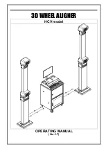
ALU4
1. Turn on machine
2.
Input a,b,d value
3.
Press ALU button, indicator lit up
4.
Start spin, after spin stop
Clip on weight on
inside rim edge, add
adhesive weight on
outside rim shoulder
ALU5
1. Turn on machine
2. Input a,b,d value
3. Press ALU button, indicator lit up
4. Start spin, after spin stop
Add adhesive weight
on inside rim shoulder,
clip on weight on
outside rim edge
ALUS
1. Turn on machine
2. Press ALU button, indicator lit up
3. Input aI,aE,d value
4. Start spin, after spin stop
Add adhesive weights
on the two positions
gauge head touch
Static mode
1. Turn on machine
2. Input a,b,d value
3. Press ALU button, indicator lit up
4. Start spin, after spin stop
Add adhesive weight
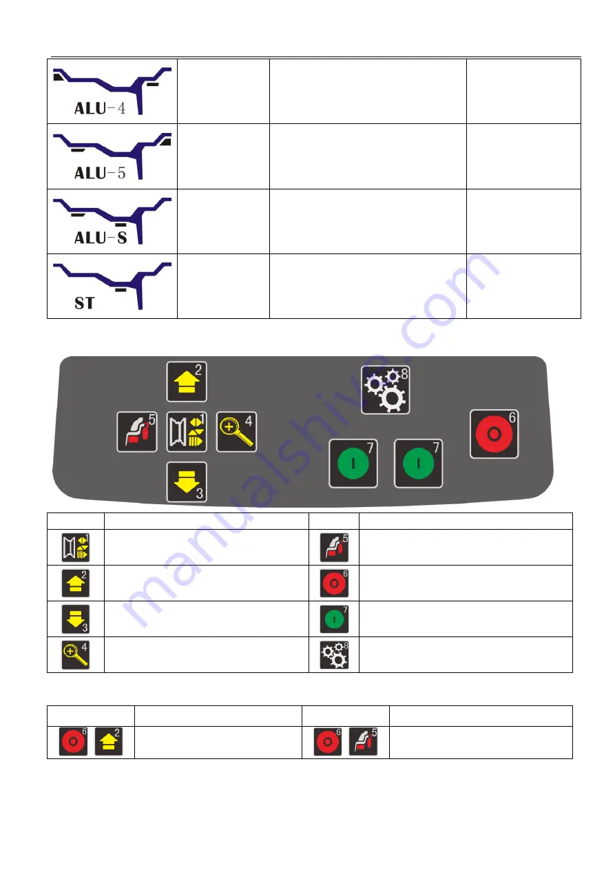
Key board(H)
Icon
Function
Icon
Function
Input rim data
Selection of “ALU” modes
Data add key
Stop/Cancel
Data reduction key
Start
Unbalance display pitch and threshold
Setting
Key combination function
Icon
Function
Icon
Function
+
Inch/mm conversion
+
OPT function