background image

25

�me (hour), the one which come

s

first

should govern.

• If you have missed the schedul

ed �me

to maintain your engine, do it as soon as

possible.

WARNING

Stop the engine before servicing. Put the

engine on a level surface and remove the

spark plug cap to prevent the engine

from star�ng

. Do not operate the engine

in a poorly ven�lated room or other

enclosed area. Be sure to keep good

ven�la�on in working area. The exhaust

from the engine may contain poisonous

CO, inhala�on can caus

e shock,

unconsciousness and even death.

CLEANING THE GENERATOR

Never clean the generator when it is

running! Never clean with a bucket of

water or a hose. Water can get inside the

working parts of the generator and cause

a short circuit or corrosion.

Always try to use the generator in a cool,

dry place. If the generator becomes dirty,

clean the exterior with a damp cloth, a

so� brush, a vacuum or pressurized air.

CHECKING THE OIL

Check the oil level of the generator

according to the Recommended

Maintenance Schedule in Fig.51. The

generator is equipped with an automa�c

shutoff to protect it from running on low

oil. The generator should be checked

before each use for proper oil level. This

is a cri�ca

l

 step for proper engine star�ng.

To check the oil level:
1. Make sure the generator is on a level

surface.
2.

Open

 access panel. Clean around 

oil fi

ll.

Remove dips�ck and wipe the dips�

ck

with a clean rag. Insert the dips�ck i

nto

the oil fill opening without sc

rewing in.

Remove the dips�ck to check the oil

mark. Add oil if the oil mark covers less

than one half of the dips�ck.

3. Slowly add more oil and repeat step 2

un�l the oil mark reaches to the top of

dips�ck . Do not over fill the crankcase.
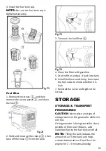
Fig.52

Oil Fill Opening, Dips

ck and Oil Level

4.

Reinstall oil dips�ck and access 

panel.

CHANGING/ADDING OIL

Avoid draining the engine oil immediately

a�er stopping the engine

. The oil is hot

and should be handled with care to avoid

burns.

Change the oil according to the

Recommended Maintenance Schedule in

Fig51. Change the oil when the engine is

warm. This will allow for complete

drainage. Change oil more o�en if

opera�ng under heavy load or h

igh

ambient temperatures. It is also

necessary to drain the oil from the

crankcase if it has become contaminated

with water or dirt. The oil capacity of the

generator engine is 0.37 qts. Add oil

when the oil level is low. For proper type

and weight of oil refer to “add oil”

por�on of the “Generato

r

Prepara�on”

sec�on.

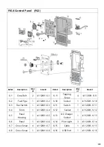
Summary of Contents for R2000i

Page 1: ...ce the risk of injury user must read this manual before assembling opera ng and maintaining this unit You are responsible for opera ng the product properly safely Version V1 20170921 2000W DIGITAL INV...

Page 2: ...iew Part List 41 SAFETY RULES Read and observe all warnings cau ons and instruc ons on the generator and in this owner s manual before opera ng your generator NOTE The following safety informa on is n...

Page 3: ...or ba ery backup CO alarm in your house If you start to feel sick dizzy or weak a er the generator has been running move to fresh air RIGHT AWAY See a doctor You could have carbon monoxide poisoning W...

Page 4: ...and disconnect any malfunc oning devices from generator Do not exceed the wa age capacity of the generator by plugging in more electrical devices than the unit can handle Do not turn on electrical de...

Page 5: ...AS MIXTURE READ INSTRUCTIONS IN OWNER S GUIDE BEFORE USING CHARGER Never use it indoor Fig 1 Never use it in a wet condition Fig 2 Never directly connect it to a house power system Fig 3 Keep it at le...

Page 6: ...pproved grounding electrode Any improper connec on may cause damage to the generator or cause a re Fig 8 Fig 9 Fig 10 GENERATOR GROUND CIRCUIT In order to prevent electric shock due to shoddy electric...

Page 7: ...Protector USB Port 5V 1 A 2 1A Phase Single Engine Engine Type Single cylinder 4 stroke forced air cooling OHV Displacement cc 79 7 Fuel Type Unleaded Gasoline Fuel Tank Capacity 1 US gallon 4 liters...

Page 8: ...ERATOR Fig 12 Carrying handle Recoil starter Fuel tank cap Oil ller cap Fuel tank cap air vent knob Louver Control panel Mu er ACCESSORIES 12V DC Ba ery charging cable 1 Spark plug socket 1 Oil funnel...

Page 9: ...arning light 7 AC receptacle 2 AC pilot light 8 Fuel cock knob 3 Overload indicator light 9 Ground earth terminal 4 Engine switch Red 10 Choke knob 5 Economy control switch Black 11 DC protector 6 USB...

Page 10: ...ses Then the AC protector will trip stopping power genera on in order to protect the generator and any connected electric devices The AC pilot light Green will go o and the overload indicator light Re...

Page 11: ...d less noise 2 OFF When the ECS switch Black is turned to OFF the engine runs at the rated speed 5000r min regardless of whether is a load connected or not NOTE The ECS switch Black must be turned to...

Page 12: ...35 liters For general use above 40 F we recommend 30W 4 stroke engine oil Do not start the engine ll ll with the su cient engine oil Engine Oil Recommendations Select good quality detergent oil beari...

Page 13: ...which can cause severe burns or even death if ignited A nearby open flame can lead to explosion even if not directly in contact with gasoline Use fresh within 30 days from purchase lead free gasoline...

Page 14: ...the CARBURETTOR when storing the product for over 30 days Step 3 GROUND THE GENERATOR WARNING Failure to properly ground the generator can result in electrocu on Ground the generator by ghtening the g...

Page 15: ...werful voltage which can result in electrocu on ALWAYS ground the generator before using it see the Ground the Generator por on of the Generator Prepera on sec on Generator should only be plugged into...

Page 16: ...unit operates normally a er the above me period while the ECS switch Black is ON ECO MODE IDLE CONTROL SWITCH This generator is equipped with an Eco Mode Idle Control Switch Engaging the switch will...

Page 17: ...ON CHECK WARNING If any item in the Pre opera on check is not working properly have it inspected and repaired before opera ng the generator The condi on of a generator is the owner s responsibility Vi...

Page 18: ...L Before star ng the generator check to see that there is su cient gasoline in the fuel tank Add addi onal gasoline as necessary but leave su cient room in tank for expansion WARNING This generator ma...

Page 19: ...the equipment grounding conductor The frame of the generator shall be connected to an approved grounding electrode For power outages permanently installed sta onary generators are be er suited for pr...

Page 20: ...g a rated running wa age equal to or less than the rated wa age of the generator Never connect devices requiring a rated wa age e qual to the surge wa ageof the generator This can trip the circuit pro...

Page 21: ...l tude lower air pressure at higher al tude and humidity The output of the generator is reduced when the temperature the humidity and the al tude are higher than standard atmospheric condi ons Addi on...

Page 22: ...C protector turns o again top charging the ba ery immediately and consult our company authorized dealer NOTE Follow instruc ons in the owner s manual for the ba ery to determine the end of ba ery char...

Page 23: ...llers PC Electronic computers microcomputer based equipment or ba ery chargers keep the generator a su cient distance away to prevent electrical interference from the engine Also ensure that electrica...

Page 24: ...ars change if necessary Cylinder head piston Clean up carbon 225cc every 125hrs 225cc every 250hrs The installa on and major repair work shall be carried out only by our authorized dealer or other or...

Page 25: ...e checked before each use for proper oil level This is a cri cal step for proper engine star ng To check the oil level 1 Make sure the generator is on a level surface 2 Open access panel Clean around...

Page 26: ...damage Keep generator level 6 Fill the crankcase with fresh oil Using a funnel or appropriate dispenser add the correct amount of oil into the crankcase The engine is equipped with a low oil pressure...

Page 27: ...5 Remove the screws and then remove the access panel Fig 58 6 Drain the fuel from the carburetor by loosening the drain screw on the carburetor oat chamber Fig 59 7 Turn the engine switch to STOP Fig...

Page 28: ...Spark Plug E6TC E6RTC Spark Plug Gap 0 6 0 7mm 0 024 0 028in 6 If re using the spark plug use a wire brush to clean any dirt from around the spark plug base then re gap the spark plug 7 Install the s...

Page 29: ...new one if the element is damaged 5 Good element can be washed in soapy water dried and reused CAUTION Do not wring out the foam element when squeezing it This could cause it to tear 6 Oil the foam el...

Page 30: ...its on the mu er screen and spark arrester using a wire brush CAUTION When cleaning use the wire brush lightly to avoid damaging or scratching of mu er screen and spark arrester Fig 71 4 Check the mu...

Page 31: ...and put it back into tank 6 Install the hose and clamp then open the fuel valve to check whether it is leak 7 Reinstall the cover and ghten the screws STORAGE STORAGE TRANSPORT PROCEDURES CAUTION Nev...

Page 32: ...32 t Drain the fuel tank d D Drain the carburettor Change oi Do not obstruct any ventilation openings Keep the generator in a cool dry area t x d d x E ENGINE W Z t W Z W d d...

Page 33: ...intenance Get a professional engine tune up at an authorized small engine repair shop Generator was lted when adding oil or shipped side down Remove spark plugs turn o engine switch then pull recoil s...

Page 34: ...Perform these steps 1 Turn o all electrical devices 2 Unplug all electrical devices 3 Shut down the engine 4 Wait several minutes and then start the engine 5 Try connec ng fewer electrical loads to th...

Page 35: ...35 WIRING DIAGRAM...

Page 36: ...Tapping Screw 5 A112001 1 2 1 5 Fuel Pipe 1 A112001 1 5 1 3 Cap 1 A112001 1 3 1 6 Flange Bolt 1 A112001 1 6 FIG 2 Tank Fuel F01 Refe Descrip on Qty pc Stock Refe Descrip on Qty pc Stock 2 1 Fuel Tank...

Page 37: ...2 3 6 Alternator Cover 1 A112001 3 6 3 3 Muffle Cover 1 A112001 3 3 3 7 Tapping Screw 3 A112001 3 7 3 4 Tapping Screw 4 A112001 3 4 3 8 5 Rubber Parts 1 A112001 3 8 FIG 4 Cover and Panel F61 Refe Des...

Page 38: ...18 FIG 5 Baseplate Inverter And Inverter Frame F61 Refe Descrip on Qty pc Stock Refe Descrip on Qty pc Stock 5 1 M6X18 Screw 4 A112001 5 1 5 9 13 Rubber Part 1 A112001 5 9 5 2 3 Rubber Parts 4 A11200...

Page 39: ...6 10 Socket 1 A112001 6 10 6 3 Fuel Switch 1 A112001 6 3 6 11 Switch 1 A112001 6 11 6 4 Shim 1 A112001 6 4 6 12 Socket 1 A112001 6 12 6 5 Panel Housing 1 A112001 6 5 6 13 DC Charger Socket 1 A112001 6...

Page 40: ...1 Flange Bolt 5 A112001 7 1 7 6 Flange Bolt 2 A112001 7 6 7 2 Alternator Cover 1 A112001 7 2 7 7 Pin 2 A112001 7 7 7 3 Stator ASSY 1 A112001 7 3 7 8 Flange Bolt 2 A112001 7 8 7 4 Rotor ASSY 1 A112001...

Page 41: ...Tapping Screw 5 A112002 1 2 1 5 Fuel Pipe 1 A112002 1 5 1 3 Cap 1 A112002 1 3 1 6 Flange Bolt 1 A112002 1 6 FIG 2 Tank Fuel F01 Refe Descrip on Qty pc Stock Refe Descrip on Qty pc Stock 2 1 Fuel Tank...

Page 42: ...2 3 6 Alternator Cover 1 A112002 3 6 3 3 Muffle Cover 1 A112002 3 3 3 7 Tapping Screw 3 A112002 3 7 3 4 Tapping Screw 4 A112002 3 4 3 8 5 Rubber Parts 1 A112002 3 8 FIG 4 Cover and Panel F61 Refe Des...

Page 43: ...18 FIG 5 Baseplate Inverter And Inverter Frame F61 Refe Descrip on Qty pc Stock Refe Descrip on Qty pc Stock 5 1 M6X18 Screw 4 A112002 5 1 5 9 13 Rubber Part 1 A112002 5 9 5 2 3 Rubber Parts 4 A11200...

Page 44: ...6 10 Socket 1 A112002 6 10 6 3 Fuel Switch 1 A112002 6 3 6 11 Switch 1 A112002 6 11 6 4 Shim 1 A112002 6 4 6 12 Socket 1 A112002 6 12 6 5 Panel Housing 1 A112002 6 5 6 13 DC Charger Socket 1 A112002 6...

Page 45: ...2 Alternator Cover 1 A112002 7 2 7 7 Pin 2 A112002 7 7 7 3 Stator ASSY 1 A112002 7 3 7 8 Flange Bolt 2 A112002 7 8 7 4 Rotor ASSY 1 A112002 7 4 7 9 Flange Nut 1 A112002 7 9 7 5 Fan 1 A112002 7 5 7 10...

Reviews: