


11
connected to the generator is opera�ng
and current above the rated
flows. To use
this equipment again, turn on DC
protector by pressing its
bu�on to “ON
”.
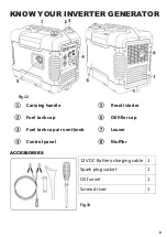
1.
“ON
”: Direct current is output.
2.
“OFF
”:Direct current is not output.
Fig.19
CAUTION:
Reduce the load of the connected electric
device below the specified rate
d output of
the generator if the DC protector turns
off.
If the DC protector turns
off again, stop
using the device immediately and consult
customer service center.
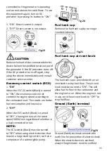
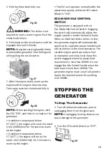
Economy control switch (ECS)
1.
“ON”
When the ESC (5
)
switch(Black
)
is turned
to “ON”, th
e economy control unit
controls the engine speed according to
the connected load. The results
are be�er
fuel consump�on and less no
ise.
2.
“OFF”
When the ECS switch (Black
)
is turned
to“OFF”, the engine runs at the rated
speed 5000r/min regardless of whether is
a load connected or not.
NOTE:
The ECS switch (Black
)
must be turned
to“OFF
” when using electric devices that
require a large star�ng current
, such as a
compressor of a submergible pump.
Fig.20
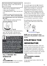
Fuel tank cap
Remove the fuel tank cap by turning it
counterclockwise.
Fig.21
Fuel tank cap air vent knob
Fig.22
The fuel tank cap is provided with an air
vent knob
to stop fuel flow.
The air vent
knob must be turned
to “ON”. This will
allow fuel to flow to the carbu
retor and
the engine to run. When the engine is not
in use, turn the air vent knob to “OFF” to
stop fuel flow.
Ground (Earth) terminal
Fig.23
Ground (Earth) termina
l connects the
earth line for
preven�on of electric shock.
When the electric device is earthed,
always the generator must be earthed.
Summary of Contents for R2000i
Page 35: ...35 WIRING DIAGRAM...


