background image

5

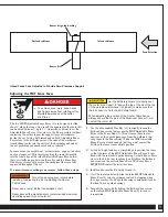
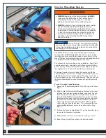
Infeed Fence Face Adjusted to Provide Zero-Clearance Support


Set the Bit Safety Guard (3) directly over 

the router bit, at least 1/2" above the top of the bit or the top 

of the workpiece (whichever is highest) to make sure that 

the bit doesn’t cut into the Bit Safety Guard.

When adjusting the position of the Router Table Fence, 

always ensure that no part of the Aluminum Fence (1) will 

contact the router bit.

Outfeed subfence

Infeed subfence

Router bit guide bushing

Router Bit

Feed Direction

>

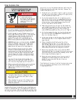
  To avoid serious injury, keep hands 

  and fingers away from rotating cutter. 

  Maintain awareness of the cutter 

  at all times.


Turn off and unplug your router before 

installing or adjusting the bit or adjusting the Router 

Table Fence. 

Never use a router bit that is damaged or dull. 

Never exceed the manufacturer’s recommended maximum 

operating speed for your router bit.

Adjusting the MDF Fence Faces

The two MDF Adjustable Fence Faces (2) are designed to slide 

about 2" along the fence. As a result, the opening for the router bit 

can be adjusted from 0" up to 3

3

4

". Generally, you want to set the 

Adjustable Fence Faces (2) as close to the bit as possible (without 

contacting the cutter) to provide support for your workpiece 

during the cut. Setting both infeed and outfeed Adjustable Fence 

Faces close to the bit helps prevent the ends of the workpiece 

from drifting too far into the cutter at the beginning and end of 

the cut, providing enhanced safety and cut quality. 

In some cases, you might want “zero-clearance” support to deliver 

an even cleaner cut. This involves cutting the router bit profile 

into the front edge of the infeed Adjustable Fence Face so that 

there’s virtually no gap between the cutter and the Fence Face. 

It delivers a cleaner cut because the workpiece fibers are fully 

supported throughout the cut. 

If a zero-clearance setting is necessary, follow these steps:

1.

  Use the blue-handled Hex Key (12) to slightly loosen the 

  flat-head hex screws that secure the MDF Adjustable Fence 

  Faces to the Fence Body (1). (Don’t loosen them too far, 

  however, or they could disengage from the weld nuts that 

  snug them to the Fence Body.) Slide the MDF Adjustable 

  Fence Faces outward enough that they won’t contact the 

  bit when the fence is moved into position.

2.

  Set the bit height and use a straightedge to position the fence 

  so that the faces of the MDF Adjustable Fence Faces (2) are 

  flush with the router bit’s guide bearing. Set both Fence Faces 

  close to the bit, but not touching it, and tighten the flat-head 

  hex screws on the outfeed Fence Face. The Fence Faces 


MUST NOT

 contact the bit at this time. 

3.

  Install and secure the Bit Safety Guard (3). 

4.

  Start the router and slowly slide the infeed MDF Adjustable 

  Fence Face (2) into the spinning router bit, stopping when 

  the edge reaches the bit’s guide bearing or midpoint (for bits 

  that don’t have a guide bearing). 

5.

  Turn off the router. Fully tighten the flat-head hex screws 

  on the infeed MDF Adjustable Fence Face (2) to secure 

  it in position.

Summary of Contents for ProMax Fence

Page 1: ...nstructions prior to use for important safety information Always check Rockler com to confirm that you are using the most recent version of instructions for your product ProMax Fence Instructions Effective June 2020 ...

Page 2: ...ication It is the sole responsibility of the purchaser of this product to ensure that any anyone you allow to use this product reads and complies with all instructions and safety precautions outlined in this manual prior to use Follow all standard shop safety practices including Keep children and bystanders away from the tool operating area Do NOT use power tools in explosive environments or in th...

Page 3: ...he chance of damage to the workpiece and or serious personal injury BEFORE plugging in and turning on the router always check to be sure that the MDF Adjustable Fence Faces 2 are fully secured and that the bit can rotate freely without touching the Fence Faces An exception to this is if you have set up the infeed Fence Face to provide zero clearance support for the workpiece as described in the Ad...

Page 4: ... Star Knob 2 10 5 16 Nylon Washer 3 11 Jointer Bar 2 12 Hex Key 1 13 Fence Locking Knob 1 Three different types of bolts are included for mounting the ProMax Fence to any of Rockler s router tabletops 5 16 18 x 5 T Bolts 5 16 18 x 31 2 T Bolts and 5 16 18 x 41 2 Carriage Bolts Use the bolts that work with your tabletop Set the Bit Safety Guard 3 directly over the router bit at least 1 2 above the ...

Page 5: ...ning and end of the cut providing enhanced safety and cut quality In some cases you might want zero clearance support to deliver an even cleaner cut This involves cutting the router bit profile into the front edge of the infeed Adjustable Fence Face so that there s virtually no gap between the cutter and the Fence Face It delivers a cleaner cut because the workpiece fibers are fully supported thro...

Page 6: ...scale on the end of the ProMax Fence Yellow tape on the top of the black part of the fence also will become visible as you adjust the fence face outward Note that the middle of the fence where the bit is located will move about half the distance shown with the the indicator lines We recommend that you make small adjustments to sneak up on the right setting Fig 2 3 Tighten the Fence Locking Knob 13...

Page 7: ...g contact with the bit Adjust the Bit Safety Guard 3 8 Plug in the router and make a test cut in scrap stock If adjustments are needed unplug the router and use the ProMax Fence s micro adjust function to fine tune the fence position THESE WARNINGS PERTAIN TO ALL REMAINING STEPS To avoid serious injury keep hands and fingers away from rotating cutter Maintain awareness of the cutter at all times T...

Page 8: ...Distributed by Rockler Companies Inc 4365 Willow Dr Medina MN 55340 53798 Rev 06 20 1 800 279 4441 www rockler com ...

Reviews: