

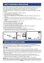


INSTALLATION INSTRUCTIONS
-WIRING
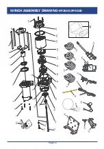
Page 2
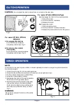
1). Plan a route for the wiring from the point of the vehicle where the winch will be mounted, or
used, to the battery. This route must be secure, out of the way of moving parts, road debris, or any
possibility of being damaged by operation or maintenance of the vehicle. For example, you may
wish to route the wires under the vehicle, attaching it to the frame using suitable fasteners. Do not
attache the wires to the exhaust system, drive shaft, emergency brake cable, fuel line, or any other
components which may create damage the wiring through heat or motion, or create a fire hazard.
2). If you drill through the bumper or any part of the body to route the wires, be sure to install a
rubber grommet in the hole to prevent fraying of the wires at that point.
3). Route the Cables from the Solenoid to the battery and from the Solenoid to the Winch,
following the precautions discussed earlier.
4). Attach the wires from the Solenoid to the terminals on the Winch.
5). Attache the Circuit Breaker(supplied to special order) to the positive terminal on the battery.
6). Attach the red Battery Cable to the Circuit Breaker.
7). Attach the black Battery Cable directly to the negative terminal of the battery.
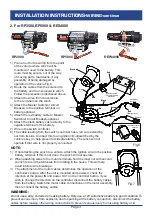
1. For RP2000 & REW2000
Fig. 4
2) Option 2- switch control (see Fig.5)
1). Connect 2 short cables to motor terminals.Red cable to motor terminal marked in red. Black
cable to motor terminal marked in black.
2). Connect 2 long cables to 2 battery terminals. Red cable to battery positive terminal. Black
cable to battery negative terminal.
1)
Option 1- solenoid and wireless remote control (see Fig.4)
RP2000
REW2000(stainless steel)
Fig.5
BATTERY
CONTROL
BOX
winch motor
Circuit Breaker
(optional)
Wireless Remote
Controller
+
_
+
_
Red
Red
Black
Black
Black
Red
Black
Red
BATTERY
+
-
+
-


