


ROCK
-
SLIDE ENGINEERING
6
**
Refer to wiring diagram for color code per door**
Run the passenger portion of the harness along the rear driver side
panel, behind the rear seat, to the passenger side. Leave the 18 pin
connector under the rear passenger seat. Run the
green/grey
wire
Toward the b
-
pillar on the passenger front.
Leave
blue/white
wire
near the rear passenger door jam
.
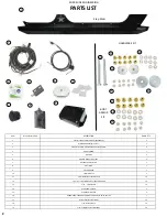
Pull back the carpet behind the driver side. Locate hole
to run the motor wires.
Remove plug from hole.
Drop the motor wire and light
wires through the hole.
Slit the plug so the plug
sits around the wire.
Repeat on the driver
side of the vehicle.
route remaining harness under
rear seat towards
the driver side
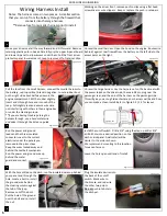
Install door sensors (# 12) . Clean under the door latch hook with an
alcohol swab and put double sided tape on, then attach sensor. Do
this to all 4 doors. Ensure wire faces inside the jeep.
Working on front passenger side, tuck the
Green/gray
wire under panels and secure. Connect
Green/gray
wire to front door sensor. Secure wires
.
Working on the rear passenger,
pull back the carpet and run
blue/white
c
onnector towards latch. Connect
door sensor to
blue/white.
Repeat the previous step on the driver side front door using the
orange/yellow
wire
.
Ensure wires are tucked away and
do not interfere with seatbelt mechanisms. Connect sensor to the
harness.
Install sensors into harness rear doors using
orange/purple
on the
driver side.
With the door sensors all connected and installed, we will install the
motor section of the harness. Ensure the motor wires have been run
through the plug and are hanging loosely below the jeep. Run motor
wires and light wires toward the rear of the jeep. Cover wires with
wire loom. Connect motor wire to harness.
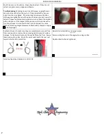
Install light kit onto the step slider (Optional—SL
-
LK
-
LED).
Put magnets onto the door in location shown on all four of the
doors. Door location may vary slightly against sensor location.
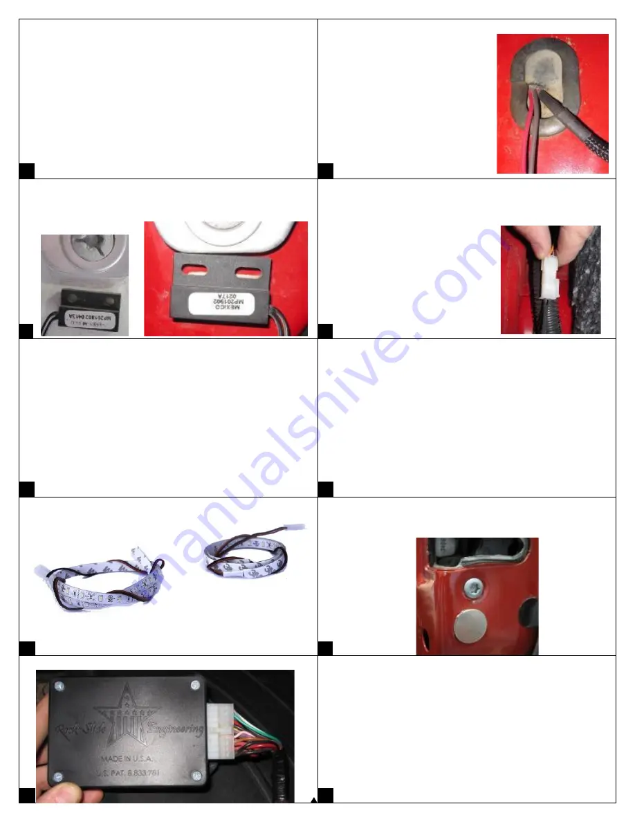
Plug circuit board into the harness.
Re
-
install fuse into the harness. Turn on the switch.
Steps should deploy at this time.
If they do not deploy see trouble-
shooting guide at the end of the instructions
20
21
22
23
24
25
26
27
28
29
Figure 6.21.1
Figure 6.22.1
Figure 6.22.2
Figure 6.23.1
Figure 6.26.1
Figure 6.27.1
Figure 6.28.1


