First start-up
20
5
by the TAC.
After performing the remedial actions (the installer's re-
sponsibility), if the TAC deems that safety and conformity
conditions are in place, first start-up may be effected.
5.2
CHECKING BURNER GAS PRESSURE
Paragraph reserved exclusively to TACs.
The gas supply circuit is equipped with a gas so-
lenoid valve with double safety shutter and pres-
sure regulator to control the gas flow. All models
are factory-set to operate with natural gas and can
be converted to LPG (see Paragraph 5.3
Each gas-fired convector is calibrated during fac-
tory testing for operation with natural gas. After
installation, check that the gas pressure at the
burner complies with indications in Paragraph
5.2.1
Natural gas supply
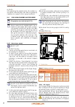
Figure 5.1
1. Remove the casing.
2. Connect a pressure gauge to the pressure intake A, af-
ter removing its sealing screw.
3. To adjust the gas pressure, the gas-fired convector
must be switched off, then access the "advanced set-
tings menu" and the submenu "transparent control
parameters" as described in the relevant Paragraph
5.4.2
4. Activate the function "valve calibration" by turning
the knob until the parameter P002 is displayed; then,
using the knob (press – rotate – press), change the
parameter value to 15: previous valve settings will be
deleted.
5. Wait until the value 20 appears on the display (the gas-
fired convector will turn on).
6. Turn the knob to display the parameter P03 "gas pres-
sure calibration at maximum power".
7. Press the knob and increase the displayed value by 1
to 5 points at a time (this operation may be repeated
several times), until the pressure gauge reads 8 mbar;
then proceed in small increments (+1) up to the re-
quired maximum pressure value (Table 5.1
p. 20).
Be careful not exceed the required gas pressure! If
this happens, you must repeat the calibration pro-
cedure (starting from step 4).
8. Turn the knob to display the parameter P04 "gas pres-
sure calibration at minimum power".
9. Press the knob and change the displayed value, start-
ing with minimal decrements (-1); press the knob
to confirm and wait for the pressure gauge read-
ing. Proceed in this way (with minimal decrements)
down to the required minimum pressure value (Table
p. 20).
10. Save the new parameter settings by turning the knob
to display parameter P002 and then pressing it to
confirm.
11. Deactivate the "valve calibration" function by turning
the knob and pressing it to set parameter P002 to "0":
the gas-fired convector will switch off.
After the adjustment, stop and start the appliance
and check that burner pressure has stabilised. If
necessary perform the adjustment again.
12. Disconnect the pressure gauge and refit the sealing
screw.
13. Replace the casing.
Figure 5.1
Pressure intake
A Pressure intake
A
Table 5.1
Burner gas pressure
42M
52M
Installation data
Burner gas
pressure
Nominal
heat input
G20
mbar
10,5
9,0
G30
mbar
28,8
28,0
G31
mbar
36,7
35,5
Minimal
heat input
G20
mbar
6,0
5,0
G30
mbar
14,0
14,7
G31
mbar
18,0
19,7
5.2.2
LPG supply
For LPG supply, the gas-fired convector must be converted
from natural gas to LPG by using the supplied gas change
kit and following the instructions in Paragraph 5.3
When operating with LPG gas, the maximum operating
pressure depends only on the network pressure, which
must be as indicated in Table 3.1
The reduction of the pressure in the network is
possible following the instructions in Paragraph


