


Heating engineer
12
3
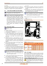
Figure 3.1
Gas supply position
A Gas connection
A
The connection to the gas mains must be made
using a rigid copper or steel pipe and fittings; alter-
natively, a flexible stainless steel pipe conforming
to the regulations in force may also be used.
The connection to the gas pipe must be properly
sealed to ensure tightness using a sealant that
complies with EN 751-1 and EN 751-2. The connec-
tion must be made in such a way that no strain is
produced in the pipe or gas-fired convector com-
ponents.
3.3.2
Mandatory shut-off valve
▶
Provide a gas shut-off valve (manual) on the gas supply
line, next to the appliance, to isolate it when required.
▶
Provide a three-piece pipe union.
▶
Perform connection in compliance with applicable
regulations.
3.3.3
Gas pipes sizing
The gas pipes must not cause excessive pressure drops
and, consequently, insufficient gas pressure for the
appliance.
3.3.4
Supply gas pressure
This appliance is equipped for a maximum gas
supply pressure of 50 mbar.
The appliance's gas supply pressure, both static and dy-
namic, must comply with Table 3.1
p. 12, with tolerance
± 15%.
Non compliant gas pressure (Table 3.1
may damage the appliance and be hazardous.
Table 3.1
Network gas pressure
Gas supply pressure [mbar]
Product category
Countries of destination
G20
G30
G31
G30
G31
II
2H3B/P
AL, BG, CH, CZ, DK, EE, FI, HR, LT, LV, MK, RO, SE, SI,
SK, TR
20
30
30
AT, CH
20
50
50
II
2H3P
BG, EE, HR, LT, SI, SK
20
37
II
2H3+
CZ, ES, GB, GR, IE, IT, PT, SK
20
28-30
37
I
3+
FR, BE
28-30
37
II
2H3B/P
HU
25
30
30
II
2HS3B/P
HU
25
30
30
II
2E3B/P
LU
20
50
PL
20
37
37
DE
20
50
50
I
2H
LV
20
I
3P
NO
30
I
3B/P
MT, CY
30
30
I
3B
30
The appliance gas supply pressure, both static and dynamic, must comply with the values in the Table, with a tolerance of ± 15%.
3.3.5
Vertical pipes and condensate
▶
Vertical gas pipes must be fitted with siphon and dis-
charge of the condensate that may form inside the
pipe.
▶
If needed, insulate the piping.
3.3.6
LPG pressure reducers
With LPG the following must be installed:
▶
A first stage pressure reducer, close to the liquid gas
tank.
▶
A second stage pressure reducer, close to the appli-
ance.
Pressure reducers must always be installed outside
the building.