Heating engineer
Installation, use and maintenance manual – Caldaia 55.1 and 100.2 Tech
21
3
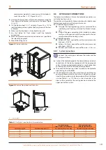
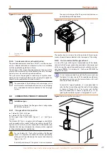
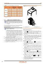
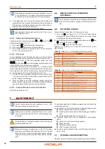
Figure 3.4
Condensate drain siphon
P
Fastening screw
T
Top point
T
P
3.3.4
Condensate drain and neutralisation
The provided condensate drain hose (EN 677) must be connect-
ed to a suitable collection and disposal system in accordance
with the applicable regulations in force.
The designer will be responsible, depending on the power of the
plant and the intended use of the building, to assess the adop-
tion of systems for neutralizing acid condensate.
The system must be designed in such a way as to prevent con-
densation from freezing. Before commissioning the appliance,
check that the condensate is drained correctly.
The connection of the discharge to the sewerage system
must be made at atmospheric pressure, i.e. by dripping
into a siphoned container connected to the sewerage
system.
3.4
COMBUSTION PRODUCTS EXHAUST
Installation types
For this type of boiler the flue gas exhaust configuration
B23P, B33 can be used.
3.4.1
Flue gas exhaust connection
▶
Caldaia 55.1 Tech: Ø 80 mm
▶
Caldaia 100.2 Tech: Ø 100 mm
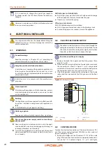
on the upper side of the boiler (Figure 1.1
p. 7 and Figure
1.4
The Caldaia 55.1 Tech is supplied with a flanged socket (60/80
mm), complete with a socket for flue gas analysis (detail PF in
Figure 5.8
p. 32), which must be connected to the combustion
chamber after having interposed the silicone gasket, supplied,
for the protection against weathering.
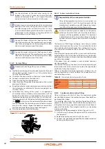
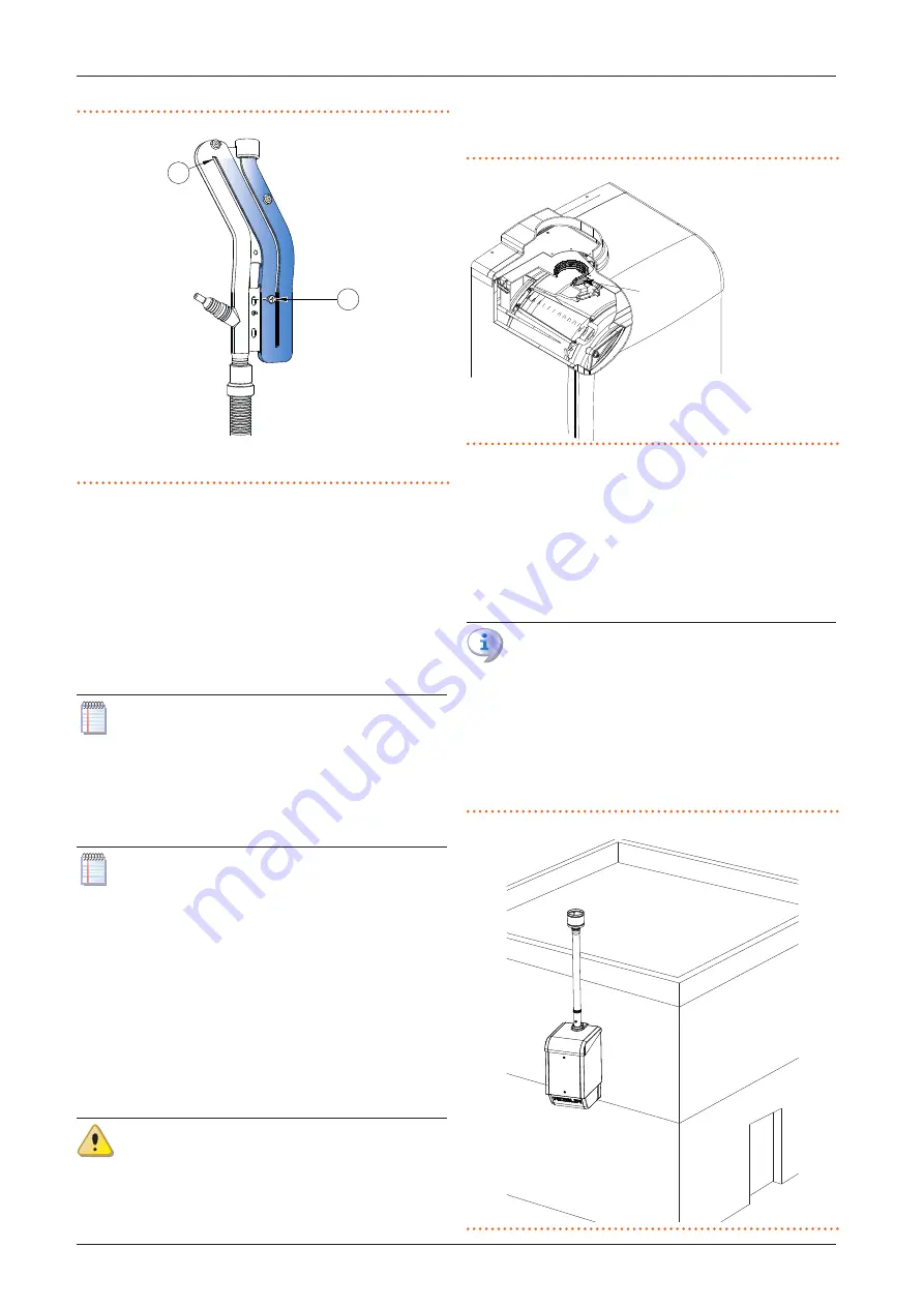
For the Caldaia 55.1 Tech: after installing the flanged
socket, it is important to check the correct positioning
of the gasket G positioned on the combustion chamber
(Figure 3.5
p. 21).
Incorrect positioning of the gasket G can compromise
the correct discharge of the flue gas outside and conse-
quently damage the appliance.
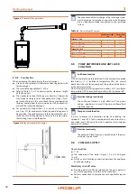
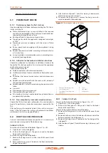
Figure 3.5
Correct gasket positioning
G
Gasket
G
The combustion air is drawn from the outside of the casing by
means of special louvres located in the lower part of the casing.
3.4.2
How to realize the flue gas exhaust
In case of flue gas discharge in correspondence of the boiler,
connect to the flue gas connection provided on the upper part
of the casing the special rainproof terminal, available as an op-
tion (code OTRM031 for Caldaia 55.1 Tech, code OTRM009 for
Caldaia 100.2 Tech).
It is not recommended to install the flue terminal near
the boiler if it is close to a wall. This condition could cause
condensation to form on the terminal and on the wall
that would fall on the boiler.
To avoid this type of problem, it is recommended to
take the flue terminal beyond the roof of the building
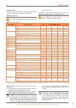
as shown in Figure 3.6
p. 21 or to carry out the flue
exhaust horizontally as shown in Figure 3.7
p. 22, re-
specting the indications given in Paragraph 3.4.3
Figure 3.6
Roof vertical flue gas exhaust


