9
CHAPTER 2
Radio Control System
The Radio Control System consists of the control transmitter unit held by the operator and the
receiver with its associated components in the robot.
The Radio Control Transmitter converts movements of the control sticks and switches into a
coded radio signal, which is transmitted by radio to the Radio Control Receiver within the robot.
The signal is received and then decoded by the micro-controller, which is on the main circuit
board in the vehicle. The micro-controller controls functions based on what was sent from the
radio control transmitter.
Radio Control Operating Instructions
Refer to the diagram showing the radio control transmitter for the location of controls. Check all
of the trim adjustments on the transmitter and make sure they are in their center position.
Extend the Radio Control Transmitter Antenna 1/4 to 1/2 way. Turn the Radio Control
Transmitter on first and then turn on the main robot power switch. It is necessary for the robot to
always have an operating signal when it is on, if there is no signal you will not have full control
of the robot.
The right hand joystick controls movement of the robot's drive wheels. Pushing the stick
forward will cause the robot to move forward. Pulling the stick back will cause the robot to move
backward. Moving the stick to the right or left will cause the robot to turn to the right or left
respectively. Movement is fully proportional so any variation or combination of movement is
possible. The horizontal and vertical trim tabs to the left and below the joystick are for centering
and should be typically left in the center. The only time that you would need to move these
trims is if the robot started moving slightly on its own. In this case move them slightly until the
robot stops.
Control of the left and right eyelids is on the left joystick. The left and right eyelids are controlled
in the corners forward and blink to the back. The eyes left and right move when you turn the
head. The eyes will look in the direction that you are turning, adding animation to the robot.
The left joystick left and right moves the Character’ head on robots with a Character driving it.
On other robots this stick controls the eyes left and right. The slider control below the stick
should be left in the center so that the head stays in the center.
For a detail of other functions, see the radio control diagram on the next page. All of these
functions are labeled on the radio control itself.
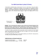
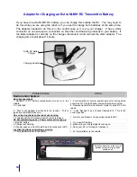
A charge plug is provided on the transmitter for recharging its internal battery. The transmitter
power switch must be in the off position before charging the batteries. A charge light on the
charger will come on while charging.
There is a RC battery (NiMH) provided with all robots. There is an extra Ni-MH battery provided
with the package. These will give you about 5 hours operation each.
Summary of Contents for Vehicle Robot
Page 53: ...49 APPENDIX A ...
Page 57: ...53 Robot Block Diagram ...
Page 58: ...54 APPENDIX B ROBOT PARTS IDENTIFICATION ...
Page 77: ...73 APPENDIX C CHECKLIST AND MAINTENANCE FORMS ...
Page 79: ...75 ...
Page 80: ...76 Notes ...
Page 81: ...77 Technical Tips ...


