RoboSense RS-Ruby Lite User Manual Download Page 75

RS-Ruby Lite Users’ Manual

18

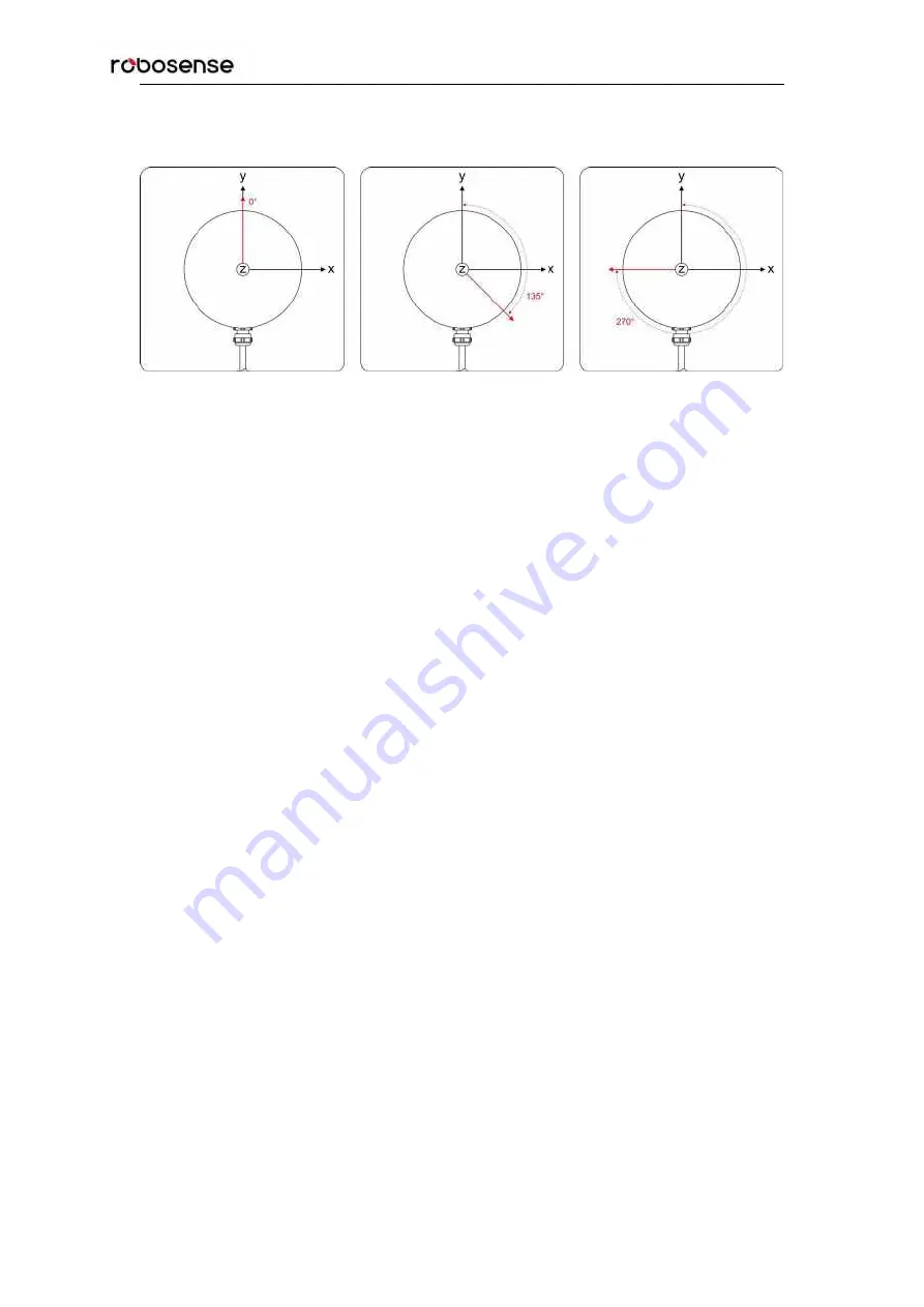
In Figure 10 different Phase Lock is shown as red arrow. When PPS is triggered, sensor can
rotate to the 0°, 135°or 270°.

Figure 10:Different phase lock angles 0°/135°/270°.

In Web sever -> Option “Setting” ->

Phase Lock Setting

, the angle of phase lock can be set in

the interval [0°~ 360°], refer to section A.2.

Summary of Contents for RS-Ruby Lite

Page 1: ...RS Ruby Lite Users Manual...

Page 2: ...RS Ruby Lite Users Manual I Revision History Version Number Description Date Edited by 1 0 0 Initial release 2020 08 03 PD...

Page 3: ...ocol GPS Global Positioning System UTC Universal Time Coordinated Wave_mode Flag of Wave Mode Temp Temperature Information Resv Reservation Symbol Symbol Bit Ret_id Identification of Return Wave Azimu...

Page 4: ...GPS Usage 13 6 2 Precision Time Protocol PTP 14 6 2 1 Principle of PTP 14 6 2 2 Topology of PTP 14 6 2 3 Time Calculation 15 7 Key Specifications 17 7 1 Return Mode 17 7 1 1 The Principle of Return M...

Page 5: ...iew 35 C 1 Software Features 35 C 2 Installation of RSView 35 C 3 Network Setup 35 C 4 Visualization of point cloud 36 C 5 Save Streaming Sensor Data into PCAP File 37 C 6 Replay Recorded Sensor Data...

Page 6: ...safety complies with IEC60825 1 2014 Read Instructions All safety and operating instructions should be read before operating the product Caution Warning hot surface Follow the Instructions All operat...

Page 7: ...R by rapidly spinning optical module Advanced digital signal processing and ranging algorithms calculate point cloud data and reflectivity of objects to enable the machine to see the world and to prov...

Page 8: ...ght 148 5mm Ingress Protection Rating IP67 Operation temperature 30 60 5 Storage temperature 40 85 1 The following data is only for mass produced products Any samples testing machines and other non ma...

Page 9: ...fined as follow Pin Wire Color Function 1 Black Brown GROUND 2 Black Gigabit network differential signal 3 Brown Gigabit network differential signal 4 Black Green GROUND 5 Red Gigabit network differen...

Page 10: ...signal input Another interface is a DC 5 5 2 1 female connector for power input The last one is a Rj45 Ethernet connector for RS Ruby Lite data transport The cable on Interface Box with Aviation conne...

Page 11: ...her the power supply is out of order or damaged If it is not intact that could prove that the Interface Box is damaged Please send the damaged Interface Box back to RoboSense Service GPS interface def...

Page 12: ...ommunication between a RS Ruby Lite and a computer the IP Address of the computer should be set at the same network segment For instance IP Address is 192 168 1 X X can be taken by a value from 1 254...

Page 13: ...last 192 byte tail The basic data structure of a MSOP packet for single return is as shown in Figure 5 MSOP Packet 1248 bytes 192bytes 80 bytes data packet 4 244bytes 976bytes 80 bytes 11th 20th Byte...

Page 14: ...Table 5 Data Block Definition Data block n 244bytes Symbol Ret_id Azimuth Channel1_data Channel80_data 1byte 1byte 2bytes 3bytes 3bytes Symbol identification bit default value 0xFE Ret_id it is used...

Page 15: ...a is as follow Get the higher 2 bytes HEX 0x08 Distance 1 0x4b Distance 2 Combine to a 16 bit unsigned integer HEX 0x084b Convert the value to decimal DEC 2123 According to the resolution 0 5 cm chang...

Page 16: ...about the device Each DIFOP packet is 1248 byte long and comprises an 8 byte Header a 1238 byte data field and a 2 byte Tail Table 7 Data Format of DIFOP Packet No Information Offset Length byte Head...

Page 17: ...Bottom Board Firmware Version 45 5 Bottom Board Software Version 50 5 Electrical Motor Firmware Version 55 5 LiDAR Hardware Version 60 3 7 Reserved 63 229 8 S N 292 6 9 Correction Value of Zero Angle...

Page 18: ...s rising edge of this PPS signal 6 1 2 GPS Usage GPS_REC receives the signal from GPS module with standard serial RS232 communication protocol The interface format of GPS_REC is SH1 0 6 female connect...

Page 19: ...Precision Time Protocol PTP 6 2 1 Principle of PTP PTP Precision Time Protocol defines a protocol enabling precise synchronization of clocks in measurement and control systems also used in different...

Page 20: ...heck the accuracy of Master Clock 3 If the connectivity is interrupted after synchronization the LiDAR time will continue counting based on the clock inside of LiDAR The LiDAR time will be reset until...

Page 21: ...tion of London time 2003 01 06 09 48 02 3 The maximum value of the nanosecond part is 0x3B9AC9FF 99999999 after the maximum value is increased by 1 the nanosecond returns to zero and the second will b...

Page 22: ...t be distinguished in the dual return 7 1 2 Strongest Return When the laser pulse hits on a near object this return signal could be considered as strongest return signal 7 1 3 Strongest Last and Dual...

Page 23: ...ock is shown as red arrow When PPS is triggered sensor can rotate to the 0 135 or 270 Figure 10 Different phase lock angles 0 135 270 In Web sever Option Setting Phase Lock Setting the angle of phase...

Page 24: ...firing sequence is the angle offset of the azimuth x y z values are the projection of the polar coordinates on the XYZ Cartesian Coordinate System The value of and can be exported per RSView in angle...

Page 25: ...al number of laser channel and corresponding horizontal angles Channel No Vertical Angle Horizontal Offset Angle 1 13 565 5 95 2 1 09 4 25 3 4 39 2 55 4 0 29 4 25 5 3 59 2 55 6 5 79 5 95 7 0 51 4 25 8...

Page 26: ...0 85 45 0 11 2 55 46 3 19 4 25 47 5 39 0 85 48 0 91 2 55 49 2 39 4 25 50 4 59 0 85 51 1 59 4 25 52 3 79 0 85 53 2 51 2 55 54 10 346 4 25 55 0 89 5 95 56 2 99 0 85 57 0 09 5 95 58 2 19 0 85 59 5 59 4 2...

Page 27: ...RS Ruby Lite Users Manual 22 73 9 244 2 55 74 0 79 4 25 75 0 01 4 25 76 0 81 4 25 77 2 49 5 95 78 15 0 85 79 1 61 4 25 80 1 69 5 95...

Page 28: ...lector Diffuse reflection reports values from 0 to 100 with the weakest reflectivity reported from black objects and strongest reflectivity reported from white objects Retro reflector reports values f...

Page 29: ...AR mounting plane is level or if the LiDAR bottom fixing screws are too tight Unit spin but no data Verify if the network wiring is functional Verify receiving computer s network settings Verify packe...

Page 30: ...ty of PPS and serial wiring Check incorrect construction of NMEA sentence Check if the GPS and Interface BOX are connected to the same GND Check if the GPS receive the valid data No data via router Cl...

Page 31: ...IP will also turn into the new IP of device A 1 Visiting Websever After correctly connecting the RS Ruby Lite with PC and configuring them use a web browser to visit the device IP default device ip 19...

Page 32: ...360 After setting FOV to a fixed region only the cloud points within this region cloud be shown 5 Rotate Speed 300rpm 600rpm default 1200rpm 6 Time Synchronization Source PTP default GPS 7 Operation...

Page 33: ...e viewed in Temperature 3 RPM shows the real time rotate speed 4 Laser Status is always On default but it is Off when Standby is active 5 In Start Times the total times of power on is recorded 6 In El...

Page 34: ...to locate it under a directory Figure A 4 Click Browser to search Firmware that needs to be updated 2 Select firmware and click Button Open Figure A 5 Select and Import Firmware to update 3 Click But...

Page 35: ...rpm clockwise rotation If set with data other than the above described the rotation speed of the motor is 0 B 2 Ethernet ETH Ethernet 22 bytes in total Byte No byte1 byte2 byte3 byte4 byte5 byte6 byte...

Page 36: ...ed to decimal B 4 Motor Phase Offset MOT_PHASE Motor Phase Offset 2bytes in total Byte No byte1 byte2 Function MOT_PHASE B 5 Top Board Firmware TOP_FRM Top Board Firmware 5bytes in total Byte No byte1...

Page 37: ...58 byte59 byte60 byte61 byte62 byte63 Function Channel 19 COR_VERT_ANG Channel 20 COR_VERT_ANG Channel 21 COR_VERT_ANG Byte No byte64 byte65 byte66 byte67 byte68 byte69 byte70 byte71 byte72 Function B...

Page 38: ...8 byte59 byte60 byte61 byte62 byte63 Function Channel 19 COR_HOR_ANG Channel 20 COR_HOR_ANG Channel 21 COR_HOR_ANG Byte No byte64 byte65 byte66 byte67 byte68 byte69 byte70 byte71 byte72 Function Byte...

Page 39: ...value to identify device B 11 Time UTC_TIME Time Register 10bytes in Total Byte No byte1 byte2 byte3 byte4 byte5 byte6 byte7 byte8 Function sec ns Byte No byte9 byte10 Function ns Note ns is in a ran...

Page 40: ...ating point cloud files in XYZ or PLY formats Function and features of RSView are shown as follow Online visualization of sensor data over Ethernet Record of real time data into pcap files Review of t...

Page 41: ...up In this dialogue box the default configuration folder of RS Ruby Lite calibration is already contained and the folder is already chosen If there is chaos while displaying in RSView please check and...

Page 42: ...File the save path and file name of pcap file can be set up Figure C 5 After clicking save button RSView begins writing data into pcap file Note RS Ruby Lite will generate enormous measuring data So...

Page 43: ...is part can be shown in table 1 Click File Open then select Capture File Figure C 6 RSView Open Capture File 2 Dialogue box Open File appears 3 In dialogue box Open File please import a recorded pcap...

Page 44: ...ich can make the display more obvious Figure C 10 Figure C 10 RSView Data Point Table 8 Click Show only selected elements in spreadsheet can acquire corresponding data certainly there is no data shown...

Page 45: ...RS Ruby Lite Users Manual 40 Figure C 13 RSView Selected Points 11 Any selected point can be saved by doing Spreadsheet Output csv data Select Frames Figure C 14 RSView Point Cloud Save...

Page 46: ...wnloaded in https github com RoboSense LiDAR rslidar_sdk or contact RoboSense technical support After download please read the README in driver packet carefully it can lead user to know how to compile...

Page 47: ...c IP address of PC is configured to 192 168 1 102 submask 255 255 255 0 gateway doesn t need configuration After configuring the static IP it can be examined in Terminal with code ifconfig D 4 Display...

Page 48: ...completely instructions to guide to read parse and visualize point cloud 1 Modify the parameters in rslidar_sdk config config yaml file set msg_source to 3 for message from pcap and fill pcap_directo...

Page 49: ...RS Ruby Lite Users Manual 44 Appendix E Dimension Figure E 1 Dimensions of Ruby...

Page 50: ...alloy in order to avoid thermolysis effects When the LiDAR is installed if there is a mounting contact surface on the upper and bottom sides of the LiDAR make sure that the spacing between the mounti...

Page 51: ...st use a clean microfiber cloth with a little isopropyl alcohol to clean the sensor directly then dry with another clean microfiber cloth If the sensor is caked with mud or bugs Firstly use a spray bo...

Page 52: ...RS Ruby Lite Users Manual 47...

Page 53: ...RS Ruby Lite Users Manual...

Page 54: ...RS Ruby Lite Users Manual I Revision History Version Number Description Date Edited by 1 0 0 Initial release 2020 08 03 PD...

Page 55: ...ocol GPS Global Positioning System UTC Universal Time Coordinated Wave_mode Flag of Wave Mode Temp Temperature Information Resv Reservation Symbol Symbol Bit Ret_id Identification of Return Wave Azimu...

Page 56: ...GPS Usage 13 6 2 Precision Time Protocol PTP 14 6 2 1 Principle of PTP 14 6 2 2 Topology of PTP 14 6 2 3 Time Calculation 15 7 Key Specifications 17 7 1 Return Mode 17 7 1 1 The Principle of Return M...

Page 57: ...iew 35 C 1 Software Features 35 C 2 Installation of RSView 35 C 3 Network Setup 35 C 4 Visualization of point cloud 36 C 5 Save Streaming Sensor Data into PCAP File 37 C 6 Replay Recorded Sensor Data...

Page 58: ...safety complies with IEC60825 1 2014 Read Instructions All safety and operating instructions should be read before operating the product Caution Warning hot surface Follow the Instructions All operat...

Page 59: ...R by rapidly spinning optical module Advanced digital signal processing and ranging algorithms calculate point cloud data and reflectivity of objects to enable the machine to see the world and to prov...

Page 60: ...ght 148 5mm Ingress Protection Rating IP67 Operation temperature 30 60 5 Storage temperature 40 85 1 The following data is only for mass produced products Any samples testing machines and other non ma...

Page 61: ...fined as follow Pin Wire Color Function 1 Black Brown GROUND 2 Black Gigabit network differential signal 3 Brown Gigabit network differential signal 4 Black Green GROUND 5 Red Gigabit network differen...

Page 62: ...signal input Another interface is a DC 5 5 2 1 female connector for power input The last one is a Rj45 Ethernet connector for RS Ruby Lite data transport The cable on Interface Box with Aviation conne...

Page 63: ...her the power supply is out of order or damaged If it is not intact that could prove that the Interface Box is damaged Please send the damaged Interface Box back to RoboSense Service GPS interface def...

Page 64: ...ommunication between a RS Ruby Lite and a computer the IP Address of the computer should be set at the same network segment For instance IP Address is 192 168 1 X X can be taken by a value from 1 254...

Page 65: ...last 192 byte tail The basic data structure of a MSOP packet for single return is as shown in Figure 5 MSOP Packet 1248 bytes 192bytes 80 bytes data packet 4 244bytes 976bytes 80 bytes 11th 20th Byte...

Page 66: ...Table 5 Data Block Definition Data block n 244bytes Symbol Ret_id Azimuth Channel1_data Channel80_data 1byte 1byte 2bytes 3bytes 3bytes Symbol identification bit default value 0xFE Ret_id it is used...

Page 67: ...a is as follow Get the higher 2 bytes HEX 0x08 Distance 1 0x4b Distance 2 Combine to a 16 bit unsigned integer HEX 0x084b Convert the value to decimal DEC 2123 According to the resolution 0 5 cm chang...

Page 68: ...about the device Each DIFOP packet is 1248 byte long and comprises an 8 byte Header a 1238 byte data field and a 2 byte Tail Table 7 Data Format of DIFOP Packet No Information Offset Length byte Head...

Page 69: ...Bottom Board Firmware Version 45 5 Bottom Board Software Version 50 5 Electrical Motor Firmware Version 55 5 LiDAR Hardware Version 60 3 7 Reserved 63 229 8 S N 292 6 9 Correction Value of Zero Angle...

Page 70: ...s rising edge of this PPS signal 6 1 2 GPS Usage GPS_REC receives the signal from GPS module with standard serial RS232 communication protocol The interface format of GPS_REC is SH1 0 6 female connect...

Page 71: ...Precision Time Protocol PTP 6 2 1 Principle of PTP PTP Precision Time Protocol defines a protocol enabling precise synchronization of clocks in measurement and control systems also used in different...

Page 72: ...heck the accuracy of Master Clock 3 If the connectivity is interrupted after synchronization the LiDAR time will continue counting based on the clock inside of LiDAR The LiDAR time will be reset until...

Page 73: ...tion of London time 2003 01 06 09 48 02 3 The maximum value of the nanosecond part is 0x3B9AC9FF 99999999 after the maximum value is increased by 1 the nanosecond returns to zero and the second will b...

Page 74: ...t be distinguished in the dual return 7 1 2 Strongest Return When the laser pulse hits on a near object this return signal could be considered as strongest return signal 7 1 3 Strongest Last and Dual...

Page 75: ...ock is shown as red arrow When PPS is triggered sensor can rotate to the 0 135 or 270 Figure 10 Different phase lock angles 0 135 270 In Web sever Option Setting Phase Lock Setting the angle of phase...

Page 76: ...firing sequence is the angle offset of the azimuth x y z values are the projection of the polar coordinates on the XYZ Cartesian Coordinate System The value of and can be exported per RSView in angle...

Page 77: ...al number of laser channel and corresponding horizontal angles Channel No Vertical Angle Horizontal Offset Angle 1 13 565 5 95 2 1 09 4 25 3 4 39 2 55 4 0 29 4 25 5 3 59 2 55 6 5 79 5 95 7 0 51 4 25 8...

Page 78: ...0 85 45 0 11 2 55 46 3 19 4 25 47 5 39 0 85 48 0 91 2 55 49 2 39 4 25 50 4 59 0 85 51 1 59 4 25 52 3 79 0 85 53 2 51 2 55 54 10 346 4 25 55 0 89 5 95 56 2 99 0 85 57 0 09 5 95 58 2 19 0 85 59 5 59 4 2...

Page 79: ...RS Ruby Lite Users Manual 22 73 9 244 2 55 74 0 79 4 25 75 0 01 4 25 76 0 81 4 25 77 2 49 5 95 78 15 0 85 79 1 61 4 25 80 1 69 5 95...

Page 80: ...lector Diffuse reflection reports values from 0 to 100 with the weakest reflectivity reported from black objects and strongest reflectivity reported from white objects Retro reflector reports values f...

Page 81: ...AR mounting plane is level or if the LiDAR bottom fixing screws are too tight Unit spin but no data Verify if the network wiring is functional Verify receiving computer s network settings Verify packe...

Page 82: ...ty of PPS and serial wiring Check incorrect construction of NMEA sentence Check if the GPS and Interface BOX are connected to the same GND Check if the GPS receive the valid data No data via router Cl...

Page 83: ...IP will also turn into the new IP of device A 1 Visiting Websever After correctly connecting the RS Ruby Lite with PC and configuring them use a web browser to visit the device IP default device ip 19...

Page 84: ...360 After setting FOV to a fixed region only the cloud points within this region cloud be shown 5 Rotate Speed 300rpm 600rpm default 1200rpm 6 Time Synchronization Source PTP default GPS 7 Operation...

Page 85: ...e viewed in Temperature 3 RPM shows the real time rotate speed 4 Laser Status is always On default but it is Off when Standby is active 5 In Start Times the total times of power on is recorded 6 In El...

Page 86: ...to locate it under a directory Figure A 4 Click Browser to search Firmware that needs to be updated 2 Select firmware and click Button Open Figure A 5 Select and Import Firmware to update 3 Click But...

Page 87: ...rpm clockwise rotation If set with data other than the above described the rotation speed of the motor is 0 B 2 Ethernet ETH Ethernet 22 bytes in total Byte No byte1 byte2 byte3 byte4 byte5 byte6 byte...

Page 88: ...ed to decimal B 4 Motor Phase Offset MOT_PHASE Motor Phase Offset 2bytes in total Byte No byte1 byte2 Function MOT_PHASE B 5 Top Board Firmware TOP_FRM Top Board Firmware 5bytes in total Byte No byte1...

Page 89: ...58 byte59 byte60 byte61 byte62 byte63 Function Channel 19 COR_VERT_ANG Channel 20 COR_VERT_ANG Channel 21 COR_VERT_ANG Byte No byte64 byte65 byte66 byte67 byte68 byte69 byte70 byte71 byte72 Function B...

Page 90: ...8 byte59 byte60 byte61 byte62 byte63 Function Channel 19 COR_HOR_ANG Channel 20 COR_HOR_ANG Channel 21 COR_HOR_ANG Byte No byte64 byte65 byte66 byte67 byte68 byte69 byte70 byte71 byte72 Function Byte...

Page 91: ...value to identify device B 11 Time UTC_TIME Time Register 10bytes in Total Byte No byte1 byte2 byte3 byte4 byte5 byte6 byte7 byte8 Function sec ns Byte No byte9 byte10 Function ns Note ns is in a ran...

Page 92: ...ating point cloud files in XYZ or PLY formats Function and features of RSView are shown as follow Online visualization of sensor data over Ethernet Record of real time data into pcap files Review of t...

Page 93: ...up In this dialogue box the default configuration folder of RS Ruby Lite calibration is already contained and the folder is already chosen If there is chaos while displaying in RSView please check and...

Page 94: ...File the save path and file name of pcap file can be set up Figure C 5 After clicking save button RSView begins writing data into pcap file Note RS Ruby Lite will generate enormous measuring data So...

Page 95: ...is part can be shown in table 1 Click File Open then select Capture File Figure C 6 RSView Open Capture File 2 Dialogue box Open File appears 3 In dialogue box Open File please import a recorded pcap...

Page 96: ...ich can make the display more obvious Figure C 10 Figure C 10 RSView Data Point Table 8 Click Show only selected elements in spreadsheet can acquire corresponding data certainly there is no data shown...

Page 97: ...RS Ruby Lite Users Manual 40 Figure C 13 RSView Selected Points 11 Any selected point can be saved by doing Spreadsheet Output csv data Select Frames Figure C 14 RSView Point Cloud Save...

Page 98: ...wnloaded in https github com RoboSense LiDAR rslidar_sdk or contact RoboSense technical support After download please read the README in driver packet carefully it can lead user to know how to compile...

Page 99: ...c IP address of PC is configured to 192 168 1 102 submask 255 255 255 0 gateway doesn t need configuration After configuring the static IP it can be examined in Terminal with code ifconfig D 4 Display...

Page 100: ...completely instructions to guide to read parse and visualize point cloud 1 Modify the parameters in rslidar_sdk config config yaml file set msg_source to 3 for message from pcap and fill pcap_directo...

Page 101: ...RS Ruby Lite Users Manual 44 Appendix E Dimension Figure E 1 Dimensions of Ruby...

Page 102: ...alloy in order to avoid thermolysis effects When the LiDAR is installed if there is a mounting contact surface on the upper and bottom sides of the LiDAR make sure that the spacing between the mounti...

Page 103: ...st use a clean microfiber cloth with a little isopropyl alcohol to clean the sensor directly then dry with another clean microfiber cloth If the sensor is caked with mud or bugs Firstly use a spray bo...

Page 104: ...RS Ruby Lite Users Manual 47...

Reviews: