background image


RU 

5

58 

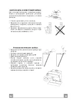
Установка


корпуса


вытяжки


• 

Откройте


створки

/

День


открытых


дверей

  (

см

Панель


разделе


Открытие

). 

• 

За


специальные


ручки


выньте


металлические


жи

-

ровые


фильтры

• 

Вставьте


два


винта


Vr


кронштейнов


11a


в


исходное


положение

• 

Повесьте


корпус


вытяжки


на

 2 

кронштейна


11a

• 

Изнутри


корпуса


вытяжки


отрегулируйте


затяжку


винтов


Vr

чтобы


выставить


корпус


по


уровню

• 

Затяните


предохранительные


винты


12a

• 

Закройте


створки

/

День


открытых


дверей


12a

Vr

11a

Соединения


ВЫПУСК


ВОЗДУХА


ИЗ


ВСАСЫВАЮЩЕЙ


ВЫТЯЖКИ


Для


установки


всасывающей


вытяжки


соединить


ее


с


выпускной


трубой


жесткой


или


гибкой


трубкой


диаметром

 150 

или

 120 

мм

тип


которой


может


вы

-

брать


монтажник

• 

Для


соединения


трубкой

 Ø 120 

мм


вставить


переходный


фланец


9


в


выпускное


отверстие


корпуса


вытяжки

• 

Закрепить


трубку


соответствующими


трубными


зажимами

Необходимый


крепежный


материал


не


входит


в


комплект

• 

Вынуть


фильтры


от


запахов


на


активном


угле


ø 150

9

ø 120

Summary of Contents for Creatix

Page 1: ...Instructions Manual Manuel d Instructions Bedienungsanleitung Manual de instrucciones Gebruiksaanwijzing...

Page 2: ...SUGGESTIONS 14 CARACTERISTIQUES 15 INSTALLATION 17 UTILISATION 21 ENTRETIEN 22 INHALTSVERZEICHNIS EMPFEHLUNGEN UND HINWEISE 24 CHARAKTERISTIKEN 25 MONTAGE 27 BEDIENUNG 31 WARTUNG 32 INDICE CONSEJOS Y...

Page 3: ...3 3 INHOUDSOPGAVE ADVIEZEN EN SUGGESTIES 64 EIGENSCHAPPEN 65 INSTALLATIE 67 GEBRUIK 71 ONDERHOUD 72 NL...

Page 4: ...department inordertopreventanyrisks Allairductingregulationsmustbecompliedwith USE Theextractorhoodhasbeendesignedexclusivelyfordomesticusetoeliminatekitchensmells Neverusethehoodforpurposesotherthanf...

Page 5: ...8 1 Directional air outlet grille 9 1 Reduction flange 150 120 16 1 Filter cover Ref Q ty Installation Components 7 2 1 2 Upper chimney fixing brackets 11 6 Plugs 11a 2 SB 12 10 Wall Plugs 12a 6 Screw...

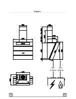
Page 6: ...EN 6 6 Dimensions Min 400mm Min 400mm...

Page 7: ...other side checking that the two marks are levelled Drill at the marked points 1 using a 12 mm drill bit Drill at the marked points 2 using a 8 mm drill bit Insert the bracket plugs 11a into the hole...

Page 8: ...r to level the hood body itself Fasten the safety screw 12a Close the doors the door again 12a Vr 11a Connections DUCTED VERSION AIR EXHAUST SYSTEM When installing the ducted version connect the hood...

Page 9: ...ir out let using the 2 screws 12d 2 9 x 9 5 provided 16 12c 12d 8 Fitting the Lighting Unit Insert the Lighting unit cable into the opening Rest the Lighting unit 9 Fix it using the Screws 12r provide...

Page 10: ...ssembly Upper exhaust Chimney Slightly widen the two sides of the upper chimney and hook them behind the brackets 7 2 1 making sure that they are well seated Secure the sides to the brackets using the...

Page 11: ...or Delay modes are active To turn it off press the button again The Leds indicating 24H speed and Motor Off turn on When the filters alarm is triggered the alarm can be reset by pressing and holding t...

Page 12: ...or at least once every 2 months use or more frequently if use is particularly intensive Resetting the alarm signal Turn the Lights and the Suction Motor off Press and hold button F 24H for 5 seconds C...

Page 13: ...l confirmation is given Motor Off Leds flash twice Activated Charcoal Filter saturation alarm ACTIVATED Motor Off Leds flash once Activated Charcoal Filter saturation alarm DEACTIVATED CHANGING THE AC...

Page 14: ...tea t con ueexclusivementpourl usagedomestique danslebutd liminerlesodeursdelacuisine Nejamaisutiliserabusivementlahotte Nepaslaisserlesflammeslibres forteintensit quandlahotteestenservice Toujoursr g...

Page 15: ...airage 8 1 Grille orientable Sortie de l Air 9 1 Buse de r duction 150 120 16 1 Couvercle filtrant R f Q t Composants de l installation 7 2 1 2 Brides de fixation chemin e sup rieure 11 6 Chevilles 11...

Page 16: ...FR 1 16 Encombrement Min 400mm Min 400mm...

Page 17: ...rifier la mise niveau Percer les points marqu s 1 avec une m che de 12 mm Percer les points marqu s 2 avec une m che de 8 mm Mettre les chevilles avec le support 11a dans les trous 1 et visser Ins re...

Page 18: ...iveau Visser les vis de s curit 12a Refermer les portes la porte 12a Vr 11a Branchements SORTIE AIR VERSION ASPIRANTE En cas d installation en version aspirante brancher la hotte la tuyauterie de sort...

Page 19: ...l l aide de 2 Vis 12d 2 9 x 9 5 fournies avec l appareil 16 12c 12d 8 Montage du groupe d clairage Introduire le c ble du groupe d clairage dans le trou Appuyer le groupe d clairage 9 Le fixer avec le...

Page 20: ...ur Montage Chemin e Chemin e sup rieure Elargir l g rement les deux bords lat riaux et les accrocher derri res les brides 7 2 1 refermer jusqu la but e Fixer lat ralement aux brides l aide des 4 vis 1...

Page 21: ...0 minutes par heure Ce mode n est pas activable si le mode Intensive ou Delay sont actifs Pour la d sactiver appuyer de nouveau sur la touche Les leds de vitesse 24Het Off moteur s clairent L alarme f...

Page 22: ...he 24H clignote ou au moins tous les 2 mois d utilisation environ ou plus fr quemment en cas d utilisation particuli rement intensive Reset du signal d alarme teindre les lumi res et le moteur d aspir...

Page 23: ...ignotements led Off Moteur Alarme saturation filtre charbon actif ACTIV E 1 clignotement led Off Moteur Alarme saturation filtre charbon actif D SACTIV E REMPLACEMENT DU FILTRE ANTI ODEUR CHARBON ACTI...

Page 24: ...n ger chenvorgesehen Unsachgem erEinsatzderHaubeistzuunterlassen Gro eFlammenbeieingeschalteterHaubeniemalsunbedecktlassen DieIntensivit tderFlammeistsozuregulieren dasssiedenTopfbodennicht berragt Fr...

Page 25: ...euchtung 8 1 Luftstromrichtungsgitter 9 1 Reduzierflansch 150 120 16 1 Filterdeckel BezugMengeInstallationskomponenten 7 2 1 2 Befestigungswinkel oberer Kaminteil 11 6 D bel 11a 2 D bel SB 12 10 12a 6...

Page 26: ...DE 2 26 Platzbedarf Min 400mm Min 400mm...

Page 27: ...te 2 mit einem Bohrer 8 mm bohren Die D bel mit dem B gel 11a in die Bohrungen 1 einf gen und festschrauben Den D bel 11 in die Bohrungen 2 einf gen Zur Montage der haube mit Dekorkamin option Den B g...

Page 28: ...ichten Die Sicherungsschraube 12a einschrauben Die Klappen wieder verschlie en Die Klappe ff nen 12a Vr 11a Anschl ss in abluftversion Bei Abluftbetrieb kann die Haube vom Installateur wahlweise mitte...

Page 29: ...Austritt der r ckzuf hrenden Luft fixieren 16 12c 12d 8 Montage der Beleuchtungseinheit Das Kabel der Beleuchtungseinheit durch das Loch stecken Die Beleuchtungseinheit 9 auf der Oberseite der Haube a...

Page 30: ...inmontage Oberer Kaminteil Die beiden seitlichen Schenkel leicht auseinanderbiegen hinter den B geln 7 2 1 einh ngen und bis zum Anschlag wieder schlie en Bei den B geln mit Hilfe der 4 mitgelieferten...

Page 31: ...von10MinutenproStundeerm glicht Dieser Modus ist nicht verf gbar wenn die Intensivge schwindigkeitoderDelayzugeschaltetist ZumAbstellendieTasteerneutdr cken Die LEDs der Betriebsgeschwindigkeit 24H un...

Page 32: ...linkt oder mindestens alle 2 Mo nate oder auch fter je nach Intensit t des Gebrauchs Reset des Alarmsignals Die Beleuchtung und den Absaugmotor abstellen Die Taste F 24H 5 Sekunden lang dr cken Reinig...

Page 33: ...n Zweimaliges Blinken der LEDs Motor Off S ttigungsalarm Aktivkohlefilter AKTIVIERT Einmaliges Blinken der LEDs Motor Off S ttigungsalarm Aktivkohlefilter DEAKTIVIERT AUSWECHSELN DES AKTIVKOHLE GERUCH...

Page 34: ...USO Lacampanahasidoconcebidaexclusivamenteparaunusodom stico paraeliminarlosoloresdela cocina Noutilizarlademanerainadecuada Nodejarllamaslibresdefuerteintensidadmientraslacampanaest funcionando Regu...

Page 35: ...ejilla orientaci n salida aire 9 1 Brida de reducci n 150 120 16 1 Cubierta filtrante Ref Cant Componentes de instalaci n 7 2 1 2 Bridas de fijaci n chimenea superior 11 6 Tacos 11a 2 Tacos SB 12 10 1...

Page 36: ...ES 3 36 Dimensiones Min 400mm Min 400mm...

Page 37: ...or la parte opuesta verificando su nivelaci n Perforar 12 mm los puntos 1 marcados Perforar 8 mm los puntos 2 marcados Introducir los tacos con bridas 11a en los orificios 1 y atornillar Introducir lo...

Page 38: ...el Cuerpo de la Campa na Atornillar el tornillo de seguridad 12a Cerrar las puertas la puerta 12a Vr 11a Conexiones SALIDA DEL AIRE VERSI N ASPIRANTE Para la instalaci n de la versi n aspirante conec...

Page 39: ...2 tornillos 12d 2 9 x 9 5 en dotaci n 16 12c 12d 8 Montaje Grupo iluminaci n Introducir el cable del grupo iluminaci n en el orifi cio Apoyar el grupo iluminaci n 9 Fijarlas con los tornillos 12r en d...

Page 40: ...e la chimenea Chimenea superior Ensanchar ligeramente las dos faldas laterales engancharlas detr s de las bridas 7 2 1 cerrarlas hasta el tope Fijar a los lados de las bridas con los 4 tornillos 12c 2...

Page 41: ...d no es activable si est activa la intensiva o la Delay Para desactivarla se presiona de nuevo la tecla Los leds de velocidad 24H yoff motor se encienden Con la alarma filtros en curso presionando la...

Page 42: ...2 meses de uso aproximadamente o con mayor frecuencia en caso de uso particu larmente intenso Reset de la se al de alarma Apagar las luces y el motor de aspiraci n Presionar la tecla F 24H por 5 segu...

Page 43: ...ecla E intensiva hasta la conformidad 2 parpadeos leds off motor Alarma de saturaci n filtro al carbono ACTIVADA 1 parpadeo led off motor Alarma de saturaci n filtro al carbono activo DESACTIVADA SUST...

Page 44: ...GR 4 44 650 mm I 120mm 0 04 mBar 2...

Page 45: ...4 45 1 1 2 1 1 2 2 1 5 1 8 1 9 1 150 120 16 1 7 2 1 2 11 6 11a 2 SB 12 10 12a 6 4 2 x 44 4 12c 10 2 9 x 6 5 12r 2 2 9 x 6 5 12d 2 2 9 x 9 5 1 11a 16 12c 12d 8 9 2 1 2 2 12c 12a 7 2 1 11 1 11 12a 12r...

Page 46: ...GR 4 46 Min 400mm Min 400mm...

Page 47: ...GR 4 47 11a 1 1 2 2 210 11 12a 247 247 1004 482 400 210 X 1 2 7 2 1 1 004 mm 1 247 mm 2 210 mm 482 mm 12 mm 1 8 mm 2 11a 1 11 2 7 2 1 1 2 mm 7 2 1 X mm X 8 mm 11 12a 4 2 x 44 4...

Page 48: ...GR 4 48 Vr 11a 11a Vr 12a 12a Vr 11a o150 120 mm o120 mm 9 150 9 120...

Page 49: ...GR 4 49 12c 2 9 x 6 5 8 2 12d 2 9 x 9 5 16 12c 12d 8 9 12r 12r...

Page 50: ...GR 5 50 3 mm 7 2 1 4 12c 2 9 x 9 5 2 12c 2 9 x 9 5 12c 2 1 2 2 2 7 2 1 12c 1...

Page 51: ...GR 5 51 Led A Led 5 Led B Led Off C Led Off D Led Off E 10 5 5 2 Led 1 Led F 24H 100 m3 h 10 Delay Led 24H Off 5 24H 100 24H 200 G Delay 30 LedDelay 5 5 2 Led 1 Led H Led 2 A B C D E F G H...

Page 52: ...GR 5 52 1 5 V LR03 AAA Led 24H 2 F 24H 5...

Page 53: ...GR 5 53 Led 24H 4 E 2 Led Off 1 Led Off F 24H 5 LED 1M EN 60825 1 1994 A1 2002 A2 2001 439nm 7 W...

Page 54: ...RU 5 54 650 I 120 0 04 2...

Page 55: ...RU 5 55 1 1 2 1 1 2 2 1 5 1 8 1 9 1 150 120 16 1 7 2 1 2 11 6 11a 2 SB 12 10 12a 6 4 2 44 4 12c 10 2 9 6 5 12r 2 4 2 12 7 12d 2 2 9 9 5 1 11a 16 12c 12d 8 9 2 1 2 2 12c 12a 7 2 1 11 1 11 12a 12r 9...

Page 56: ...RU 5 56 Min 400mm Min 400mm...

Page 57: ...RU 5 57 11a 1 1 2 2 210 11 12a 247 247 1004 482 400 210 X 1 2 7 2 1 1004 1 247 2 210 482 12 1 8 2 11a 1 11 2 7 2 1 1 2 7 2 1 X X 8 11 12a 4 2x44 4...

Page 58: ...RU 5 58 Vr 11a 2 11a Vr 12a 12a Vr 11a 150 120 120 9 150 9 120...

Page 59: ...RU 5 59 4 12c 2 9 x 6 5 8 2 12d 2 9 x 9 5 16 12c 12d 8 9 12r 12r...

Page 60: ...RU 6 60 3 7 2 1 4 12c 2 9 x 9 5 2 12c 2 9 x 9 5 12c 2 1 2 2 2 7 2 1 12c 1...

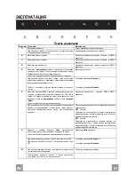
Page 61: ...RU 6 61 A 5 B C D E 10 5 5 2 A 1 A F 24H 100 3 10 Delay 24H 5 24H 100 24H 200 G Delay 30 Delay 5 5 2 A 1 A H 2 A B C D E F G H...

Page 62: ...RU 6 62 1 5 LR03 AAA 24H 2 F 24H 5...

Page 63: ...RU 6 63 24H 4 E 2 1 F 24H 5 1M EN 60825 1 1994 A1 2002 A2 2001 439nm 7...

Page 64: ...voor huishoudelijk gebruik voor het elimineren van kookgeuren Gebruik de kap nooit op oneigenlijke wijze Laat geen hoog brandende branders onbedekt onder de wasemkap terwijl deze in werking is Regel d...

Page 65: ...gsunit 8 1 Richtingsrooster luchtafvoer 9 1 Verloopflens 150 120 16 1 Filterdeksel Ref Aantal Installatieonderdelen 7 2 1 2 Bevestigingsbeugels bovenste schouw 11 6 Pluggen 11a 2 Pluggen SB 12 10 12a...

Page 66: ...NL 6 66 Buitenafmetingen Min 400mm Min 400mm...

Page 67: ...g Boor gaten van 12 mm op de plaats van de getekende punten 1 Boor gaten van 8 mm op de plaats van de getekende punten 2 Plaats de pluggen met de beugel 11a in de gaten 1 en draai ze aan Plaats de plu...

Page 68: ...veiligheidsschroef 12a aan Sluit de panelen het paneel weer 12a Vr 11a Aansluitingen LUCHTUITLAAT AFZUIGVERSIE Bij installatie in afzuigversie moet u de wasemkap met de uitlaatleiding verbinden door m...

Page 69: ...recirculeerde lucht met 2 van de bijgeleverde schroeven 12d 2 9 x 9 5 16 12c 12d 8 Montage van de verlichtingsunit Voer de kabel van de verlichtingsunit door het gat Laat de verlichtingsunit 9 op de b...

Page 70: ...ontage van de schouw Bovenstuk van de schouw De twee zijplaten enigszins openen ze vasthaken achter de beugels 7 2 1 en ze weer zo ver mogelijk sluiten Aan de zijkant aan de beugel bevestigen met de 4...

Page 71: ...chakeld alsdehogesnelheidofdelayactiefis Drukopnieuwopdetoetsomdefunctieuitteschakelen Deledsvandesnelheid24HenOffmotorgaanbranden Als tijdens het filteralarm ongeveer 5 seconden op deze toets wordt g...

Page 72: ...de led 24H gaat knipperen of in elk geval ongeveer om de 2 maanden of vaker bij veelvuldig gebruik Reset van het alarmsignaal Schakel de lampen en de zuigmotor uit Druk 5 seconden op de toets F 24H Re...

Page 73: ...ieofdaarna Schakeldelampenendezuigmotoruit DruktotdebevestigingopdetoetsE hogesnelheid 2keerknipperenvandeledsOffMotor AlarmgeurfiltermetactievekoolstofverzadigdAAN 1keerknipperenvandeledsOffMotor Ala...

Page 74: ......

Page 75: ......

Page 76: ...991 0270 997_ver1...

Reviews: