12
10-V1011
Z3200
Z3200
10-V1011
13
–
English
–
Deutsch
–
English
–
Deutsch
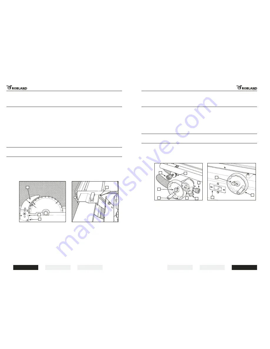
Use and adjustment
of the riving knife
(Fig.10)
The machine is equipped with two riving knives for the use of sawblades from 250 to 300 mm and 350
to 400 mm.
The riving knife has to be adjusted in such a way that over its entire length the gap between sawblade
and riving knife does not exceed min.3 mm and max.8 mm.
The riving knife can be adjusted in both vertical and horizontal direction.
The height setting has to be adjusted in such a way that the highest point of the riving knife never
exceeds more than 3 mm above the highest placed sawblade tooth.
After height adjustment always lock the central bolt (3) at a torque of 60 Nm. The 3 little adjustment
screws (2) are used for the exact setting of the riving knife in line with the sawblade.
For slotting or grooving the riving knife has to be adjusted in such a way that the upper part of the
riving knife is never set lower than the highest sawtooth in use.
Never remove this riving knife. Kickbacks are severe and very dangerous.
Lower sawblade cover
(Fig.10 bis)
The lower sawblade cover has an extra safety device which will protect the user during sawblade
changing.
To open the lower cover the upper part of the sliding table has to be slid to the back.
Now the two locks can be opened at both sides of the cover and the safety lever can be pulled up.
Only now can the sawblade cover be opened and this safety device prevents the table from being
pushed to the front, which would result in injuries to the operator’s hands.
After closing the lower cover push down the safety lever (1).
Height setting of main sawblade
and scorer sawblade
(Fig.11)
Main sawblade height setting is done by turning the handwheel (1). After the sawblade is set at the
desired cutting depth the handwheel has to be locked with the locking knob (2).
One turn of this handwheel equals 5 mm of height setting.
The height setting of the scorer sawblade is done by turning the knob (4), and locked by
turning the wheelnut (3). One turn of this height setting knob equals 3 mm.
The maximum cutting depth using a main sawblade diameter of 400 mm is 125 mm and for the scorer
4,5 mm using a sawblade diameter of 100 mm.
Tilting of the sawunit
(Fig.12)
By turning the handwheel (2) the whole sawunit can be tilted and set at any angle between 90° and
45°. After setting, lock the sawunit in this position using the locking knob (1).
The angle can be read at the large scale (3).
Both 45° and 90° positive stops are factory set and need no adjustment. After setting the
sawunit at the desired cutting angle the cutting depth of the scorer must be set again.
Fig.10
Fig.11
Fig.10 bis
Fig.12
1
1
3
3
1
1
4
2
1
7
6
5
2
3
Min 3, max 8 mm


