background image

be installed 10ft. (3m) back from discharge grille.  A flex or lined duct is recommended for
the last 5ft. (1.5m).  Robertshaw dampers are 2 position dampers.  Two wire dampers are
powered closed and spring return open.  Three wire dampers are powered closed and
powered open.  For applications requiring minimum air ventilation, an adjustment screw is
available to set the damper to a specified minimum open position.  Robertshaw dampers
are shipped from the factory with the minimum position adjustment screw in the fully
closed position; allow for 3% to 5% leakage with damper closed.  The control panel has 3
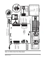
terminals for each damper which are (refer to Figure 4.2):

PC:

power damper closed

X:

common

PO:

power damper opened 

Power to the dampers is provided by the panel. 

NOTE: 

High ambient temperatures (e.g., those found in an attic), will have an impact on the

current capabilities of the panel and the number of zone dampers that can be connected to
the panel. The 2701-001 and 2701-006 are powered by a single 75 VA transformer. This
transformer is used to power the panel, thermostats and motorized dampers. The ambient
temperature will have an impact on the Polyfuse current limiting protection. The maximum
number of dampers that can be connected to the total system using Robertshaw dampers are: 

At 25ºC (77ºF)

At 40ºC (104ºF)

6 E Series dampers

5 E Series dampers

5 E2 Series dampers

4 E2 Series dampers

6 E3 Series dampers

5 E3 Series dampers

If additional dampers are required you must use a relay to energize these additional
dampers from an independent source.

4.6

BYPASS DAMPER SYSTEM

In order to maintain proper air flow and static pressure throughout the HVAC system, a
bypass system should be used.  In some 2 zone applications a bypass damper may not be
required.  This is based on duct sizing where either zone is able to handle approximately
75% of the total system CFM (cubic feet/minute).  This will result in only slightly higher air
velocity at the discharge grille if only one zone is calling and yet allow for proper CFM
across the cooling coil. In many smaller commercial and most residential zone systems, a
barometric bypass damper is all that is required to maintain proper system static pressure.
In larger systems, a motorized bypass damper with an independent static pressure control
will be required.

4.6.1 INSTALLING THE BYPASS DAMPER

The bypass damper must be installed in the main supply plenum in a straight section of
equal duct size.  The bypass air may be discharged into the return air plenum or above the
ceiling, if this area is used as a common return. 

SlimZone Classic

6

Summary of Contents for SLIMZONE CLASSIC 2701-001

Page 1: ...SLIMZONE CLASSIC 2701 001 2701 006 ZONE CONTROL SYSTEM INSTALLATION AND OPERATION MANUAL ...

Page 2: ...RMOSTAT INSTALLATION 5 4 4 WIRING 5 4 5 DAMPERS 5 4 6 BYPASS DAMPER SYSTEM 6 4 6 1 INSTALLING THE BYPASS DAMPER 6 4 6 2 BAROMETRIC BYPASS SETUP 8 4 6 3 MOTORIZED BYPASS DAMPERS 8 4 7 CURRENT LIMITED OUTPUT TERMINALS 8 4 8 HIGH AND LOW LIMITS 8 5 SYSTEM OPERATION 9 5 1 INITIAL POWER UP 9 5 2 ESTABLISHING MODE OF OPERATION 9 5 3 SEQUENCE OF OPERATION 9 6 CONTROL PANEL SETUP 10 7 LED STATUS INDICATIO...

Page 3: ...Uses conventional 2 to 5 wire thermostats LED light emitting diode indicators on all system functions Solid state logic panel with current limiting outputs Controls heat pumps cooling units and gas oil or electric furnace units Model 2701 001 controls up to 3 zones Model 2701 006 controls up to 2 zones Controls 1 stage of heating and 1 stage of cooling in heat cool applications or 1 compressor wit...

Page 4: ...er must be installed on all systems of three 3 zones Some two 2 zone systems may require a bypass damper m The thermostats and motorized dampers may be located up to 300ft 90m from the control panel when 18AWG copper thermostat wire is used n This system requires standard electromechanical or electronic heat cool thermostats Do not use heat pump thermostats because a call for compressor from the t...

Page 5: ...3 3 SIZING TRANSFORMERS To avoid unsatisfactory operation DO NOT power this control panel with the HVAC equipment transformer The rated voltage for the SlimZone Classic is 20 30 VAC 24 nominal A dedicated field supplied 24VAC 75 VA transformer is recommended to power the control panel which in turn provides power to the zones including up to a total of 5 dampers Typical zone dampers require a maxi...

Page 6: ...d potential loss of operation due to static discharge The door is hinged on the left side Open the door by gently pulling on the bottom right corner Apply finger pressure only The door may be removed once opened by applying a slight backward pressure Replace the door by hooking around the tabs on the left side of the base panel and snapping back into place SlimZone Classic 4 Classic Not available ...

Page 7: ...Backplate Mounting Holes 4 3 THERMOSTAT INSTALLATION Heat pump thermostats must not be used with the SlimZone Classic panel Zone thermostats should be installed in a location that best suits the general load characteristics of the space it will control Do not mount thermostats in hallways exterior walls or near cold air returns or registers 4 4 WIRING Use 18 AWG nonshielded copper wire for all sys...

Page 8: ... number of dampers that can be connected to the total system using Robertshaw dampers are At 25ºC 77ºF At 40ºC 104ºF 6 E Series dampers 5 E Series dampers 5 E2 Series dampers 4 E2 Series dampers 6 E3 Series dampers 5 E3 Series dampers If additional dampers are required you must use a relay to energize these additional dampers from an independent source 4 6 BYPASS DAMPER SYSTEM In order to maintain...

Page 9: ...Figure 4 2 SlimZone Classic Panel Wiring Diagram SlimZone Classic 7 ROBERTSHAW TIME DELAY OVERRIDE Zone 3 not available on 2701 006 ...

Page 10: ...caused by circumstances such as wiring shorts on an output This device referred to as a polyfuse is activated in general when the current draw exceeds 2 5 Amps The value and the duration of the excess current is taken into account The polyfuse will allow excess currents of very short duration i e spikes in order to prevent circuit interruption by noisy lines or occasional minor surges In its curre...

Page 11: ... be ignored by the panel The control panel will keep the equipment operating in the established mode for a minimum on time of 4 minutes and until all zones calling for the established mode of operation are satisfied Once all zones are satisfied the control panel will de energize the equipment and will initiate a minimum off timer of 4 minutes to prevent equipment short cycling The control panel wi...

Page 12: ... placed in the EH position the Y1 terminal output to the compressor will always be de energized and the W1 terminal will automatically replace the function of Y1 The upstaging sequence will be canceled and any call for heating will energize W1 6 CONTROL PANEL SETUP For heat cool systems gas oil or electric the control panel slide switches have the following functions Switch Position Description 1 ...

Page 13: ...gized in heating NORMAL WHEN Green Upper right corner Panel functioning properly FLASHING Table 7 1 LED Description 8 OPERATION CHECK LIST Verify that the following controls have been properly configured installed and adjusted 1 High limit 2 Low limit 3 Static pressure or barometric bypass damper 4 All thermostats low setpoint at 68 F 20 C and high setpoint at 76 F 24 C 5 Tag all wiring and system...

Page 14: ...60 times i e 1 minute is reduced to 1 second b The LEDs located on the SlimZone Classic panel should indicate the following condition System power ON Cooling ON Fan ON All zone dampers open 3 Heating Cycle Set the heating setpoints of all zone thermostats to their highest setting Note Ensure that the remote switch selector for mode of operation is not set to Cool Only if installed a The LEDs locat...

Page 15: ... Replace if necessary Improper remote switch selector Ensure the switch is set to a mode of setting if installed operation which allows the requested call to be serviced No heat cooling in Balancing damper closed Check all balancing dampers in the zone same duct as the motorized zone damper closed balancing dampers should be readjusted Zone registers closed Check all zone registers closed register...

Page 16: ...ystem A bypass system maintains uniform static pressure in the system ductwork by modulating a motorized bypass damper in the main supply duct Mode of Operation A mode is a specific operating setting Off Cool Heat Auto E Heat which can be established at the control panel and the zone thermostats Zone A defined area that is controlled by a zone thermostat and motorized zone damper Zone thermostats ...

Page 17: ... FIGURE 4 2 SLIMZONE CLASSIC PANEL WIRING DIAGRAM 7 APPENDIX B List of Tables TABLE 3 1 SLIMZONE CLASSIC COMPONENT REQUIREMENTS 3 TABLE 5 1 MODE OF OPERATION 9 TABLE 6 1 SWITCH FUNCTIONS IN HEAT COOL SYSTEMS 10 TABLE 6 2 SWITCH FUNCTIONS IN HEAT PUMP SYSTEMS 10 TABLE 7 1 LED DESCRIPTION 11 SlimZone Classic 15 ...

Page 18: ...the event of misuse abuse or as a result of unauthorized alterations or repairs The manufacturer will not be liable for any consequential damages including without limitation damages resulting from defects loss of use or misuse Compliance This equipment if installed in strict accordance with the manufacturer s instructions complies with the limits for a Class B computing device pursuant to Subpart...

Page 19: ...acustomerservice invensys com For Technical Service Telephone 1 800 445 8299 Facsimile 1 630 260 7243 technicalservice invensys com www icca invensys com 2004 Invensys Climate Controls Americas Climate Controls of Canada Inc 3505 Laird Road Unit 14 Mississauga Ontario L5L 5Y7 Canada Customer Service Telephone 1 800 387 7978 Customer Service Facsimile 1 905 828 1265 iccacustomerservice invensys com...

Reviews: