background image

3

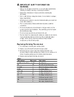
IMPORTANT SAFETY INFORMATION
WARNING:

• Always turn off power at main fuse or circuit breaker panel before

installing, removing, cleaning, or servicing thermostat.

• Read all the information in this manual before installing this

thermostat.

• This is a 24V AC low-voltage thermostat.  Do not install on voltages

higher than 30V AC.

• All wiring must conform to local and national building and electrical

codes and ordinances.

• This is a dual powered thermostat that will operate on 24V AC

or batteries.

• Do not short (jumper) across terminals on the gas valve or at the

system control to test installation.  This will damage the thermostat
and void the warranty.

• Do not connect ground to any terminal in this unit.

• This thermostat is configured with automatic compressor protection

to prevent damage because of short cycling or extended power
outages.  Short cycle protection provides a delay between
compressor cycles on heat pumps.

Replacing Existing Thermostat

1. Turn off power to heating and cooling system.

2. Remove cover from old thermostat to expose wires.

3. Disconnect wires one at a time from existing terminals.  Use

enclosed labels to mark existing wires.  Refer to cross references in
Table 1 if existing wiring does not directly match the labels.

4. Remove existing thermostat base from wall.

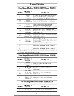
Table 1

Old Terminal

New Label

Description

R, RH/R, V-VR or VR-R 

R/RH

24V AC Return

RC

RC

24V AC Cooling Transformer

C, X or B

C

24V AC Transformer Common Side

F or G

G

Fan Control Relay

Y, Y1 or M

Y1

1st Stage Cooling Circuit

W1 or W

W1

1st Stage Heating Circuit

Y2

Y2

2nd Stage Cooling Circuit

W2 or W-U

W2

2nd Stage Heating Control

W3

E

3rd Stage Heating Control

E

E

Emergency Heating Control

Summary of Contents for RS4110

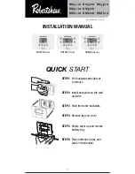
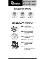
Page 1: ...2 00060 001 Rev B INSTALLATION MANUAL STEP 1 Pull backplate straight out to remove STEP 2 Install backplate on the wall and wire STEP 3 Push front onto backplate STEP 4 Remove tape on cover STEP 5 Rotate cover up and remove battery tray STEP 6 Place batteries in tray and place in thermostat QUICK START ...

Page 2: ... C The cover snaps to the top of the body and swings up to give access to the programming buttons Recycling Thermostat If this thermostat is replacing a thermostat that contains mercury in a sealed tube do not place your old thermostat in the garbage Contact your local waste management authority for instructions regarding proper disposal of the thermostat If you have any questions call Robertshaw ...

Page 3: ...matic compressor protection to prevent damage because of short cycling or extended power outages Short cycle protection provides a delay between compressor cycles on heat pumps Replacing Existing Thermostat 1 Turn off power to heating and cooling system 2 Remove cover from old thermostat to expose wires 3 Disconnect wires one at a time from existing terminals Use enclosed labels to mark existing w...

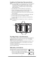
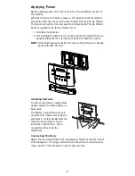
Page 4: ...nd secure the base to the wall with the supplied screws NOTE The thermostats are designed to also mount on a single gang junction box Providing Power to the Thermostat To take advantage of the Pop Up Wizard power should be applied when the settings are ready to be entered Fill in the chart in the Pop Up Wizard section before applying power These thermostats will run on either two AA batteries or 2...

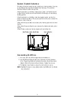
Page 5: ...ric If Non Heat Pump and Gas are selected the heating system will control the fan If Non Heat Pump and Electric are selected the thermostat will control the fan If Heat Pump is selected the thermostat will control the fan Connecting the Wires 1 The wire ends should be stripped back 8 mm 5 16 in 2 Use the Wiring Diagrams and secure the wires into the terminal strip If replacing another thermostat t...

Page 6: ...onfigured as a Non HP G Indoor fan connection Energizes with Y1 and Y2 Energizes with W1 and W2 if the Gas Elec switch is set to electric Energizes when fan is switched to ON O Energizes for heat pump cool reversing valve B Energizes for heat pump heat reversing valve This thermostat can be used as a heat only or cool only thermostat Therefore it is not always necessary to use both W1 and Y1 Two S...

Page 7: ...ling transformer is present When used as Heat Pump with Heat Active Reversing Valve With Battery Make certain the HP switch is in the HP position 24 Vac Compressor Fault Output 24VAC Second Stage Cool Second Stage Heat Not used for RS4110 RS5110 and RS6110 Not used for RS4110 RS5110 and RS6110 Emer Heat or Third Stage Heat Compressor Contactor Fan Relay G O B Y1 W1 Y2 W2 E RH R RC C L Heat Transfo...

Page 8: ...mp with Cool Active Reversing Valve With Battery Backup Make certain the HP switch is in the HP position 24 Vac Compressor Fault Output 24VAC Second Stage Cool Second Stage Heat Not used for RS4110 RS5110 and RS6110 Not used for RS4110 RS5110 and RS6110 Emer Heat or Third Stage Heat Compressor Contactor Reversing Valve Fan Relay G O B Y1 W1 Y2 W2 E RH R RC C L Transformer Hot 120 Vac Remove jumper...

Page 9: ...t has the C terminal connected and 24V AC present NOTE A thermostat powered by 24V AC will use the batteries as backup power if the 24V AC fails Installing Batteries To remove the battery compartment gently squeeze the ribbed edges on both sides The battery compartment will pull down from the thermostat body and will detach Install two AA batteries following the polarity as shown inside the compar...

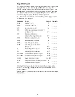
Page 10: ...n 0 5 to 3 0 F or 0 5 to 1 5 C 1 F _______ DIF2 2nd stage differential added to first stage differential 2 F _______ DLY2 2nd stage delay in minutes 20 _______ DLY3 3rd stage delay in minutes 20 _______ AUTO auto changeover enable y _______ DEDB auto changeover deadband in degrees 3 F _______ HI heat setting limit in degrees 90 F _______ LO cool setting limit in degrees 45 F _______ VAC HEAT vacat...

Page 11: ...ion Test Utility WARNING The installation test procedures can damage the heating cooling equipment if used incorrectly These procedures should only be performed by trained HVAC personnel The following instructions may be used to test the heating cooling system for correct function To enter the test mode press and hold and for five seconds Short Cycle protection is disabled when using the test util...

Page 12: ...de of operation and how to protect the settings Installation Tests for Multi Stage Models Conventional Non HP Heat Pump HP Demand Terminal Display Terminal Display First Stage Heat W1 G Y1 G B Second Stage Heat W1 W2 G 2 Y1 W2 G B 2 Third Stage Emergency Heat N A E G E First Stage Cool Y1 G Y1 G O Second Stage Cool Y1 Y2 G 2 Y1 Y2 G O 2 G will be off not displayed for Non HP with Gas Installation ...

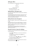
Page 13: ... is automatic As the room temperature changes the thermostat will call for heating or cooling as needed The display will flash the heat or cool symbol to show which system is active Note that the Hi Low temperature limits are not enforced in auto changeover mode Auto changeover mode can be disabled as a user option in the pop up wizard Security Lockout to Protect the Settings The buttons on the fr...

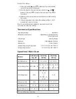
Page 14: ...gs Thermostat Specifications Operating Voltage 18 30V AC Maximum Load Current 1 Amp Max per Output Terminal 4 Amp Total Load Output Type Latching Relays Batteries 2 AA Alkaline in Series Battery Life 2 Years Typical Ambient Operating Temperature 14 F 10 C to 122 F 50 C Storage Temperature 4 F 20 C to 140 F 60 C Operational Mode Chart Demand Conventional Non HP Heat Pump HP Elec Heat Pump HP Gas Fi...

Page 15: ...ection System turns on too often Increase temperature differential see Pop Up Wizard section System fan does not operate properly Move fan option switch to either gas or electric to match system see System Switch Selection section Thermostat does not display proper room temperature Check F C Fahrenheit Celsius setting see Pop Up Wizard section Display shows HI or LO and room temperature is normal ...

Page 16: ...Repair or replacement as provided under this warranty is the exclusive remedy of the consumer Invensys Controls shall not be liable for any incidental or consequential damages for breach of any express or implied warranty on this product or under any other theory of liability Except to the extent prohibited by applicable law any implied warranty of merchantability or fitness for a particular purpo...

Page 17: ...a posterior tire directamente hacia afuera PASO 2 Instale la placa posterior sobre la pared y realice las conexiones PASO 3 Presione el frente contra la placa posterior PASO 4 Retire la cinta de la tapa PASO 5 Gire la tapa hacia arriba y retire la bandeja de la batería PASO 6 Coloque las baterías en la bandeja e instale la bandeja en el termostato COMIENZO RÁPIDO ...

Page 18: ...e encaja en la parte de superior del cuerpo y se remueve para permitir el acceso a las teclas de programación Reciclado de termostatos Si instala este termostato para reemplazar un termostato que contiene mercurio en un tubo sellado no deseche la unidad que reemplaza arrojándola a la basura Contacte a la autoridad local encargada de la disposición de desechos y pida instrucciones para desechar cor...

Page 19: ...ciclos de corta duración o cortes prolongados de suministro de energía La protección de ciclos de corta duración proporciona un retardo en los ciclos del compresor en las bombas de calor Para cambiar el termostato actual 1 Interrumpa el suministro de energía que llega a los sistemas de calefacción y refrigeración 2 Retire la tapa del viejo termostato para dejar expuestos los cables 3 Desconecte lo...

Page 20: ...a pared la ubicación de los orificios de montaje 5 Realice las perforaciones en los lugares marcados usando una broca para taladro de 5 mm 3 16 in 6 Golpee los insertos de fijación y fije la base a la pared con los tornillos provistos NOTA Los termostatos están diseñados para ser montados en una caja individual de coneciones Para llevar energía al termostato Para aprovechar las ventajas del asiste...

Page 21: ...a primera llave en la posición Non Heat Pump sin bomba de calor La segunda llave se debe ubicar para que coincida con un sistema alimentado a gas boton en posición Gas o electricidad boton en posición Electric Si elige Non Heat Pump y Gas el sistema de calefacción controlará el ventilador Si elige Non Heat Pump y Electric el termostato controlará el ventilador Si se selecciona Heat Pump Bomba de c...

Page 22: ...nexión ventilador interiores Energiza con Y1 y Y2 Energiza con W1 y W2 si la llave Gas Elec se coloca en electricidad Energiza cuando el ventilador se pone en ON O Energiza válvula inversora de refrigeración de bomba de calor B Energiza válvula inversora de calefacción de bomba de calor Este termostato se puede usar como termostato de calefacción solamente o como ter mostado de refrigeración solam...

Page 23: ... se usa como bomba de calor con válvula inversora activada en modo calefacción con pilas 24 Vac Salida falla compresor 24VCA Refrigeración segunda etapa Calefacción segunda etapa No se usa en los modelos RS4110 RS5110 y RS6110 No se usa en los modelos RS4110 RS5110 y RS6110 Verifique que la llave HP esté en la posición HP Calefacción de Emergencia o Calefacción de Tercera Etapa Contactor del compr...

Page 24: ...ación 24 Vac Salida falla compresor 24VCA Refrigeración segunda etapa Calefacción segunda etapa No se usa en los modelos RS4110 RS5110 y RS6110 No se usa en los modelos RS4110 RS5110 y RS6110 Verifique que la llave HP esté en la posición HP G O B Y1 W1 Y2 W2 E RH R RC C L Calefacción de Emergencia o Calefacción de Tercera Etapa Contactor del compresor Válvula inversora Relé del ventilador G O B Y1...

Page 25: ... a la placa posterior que tiene el terminal C conectado la unidad recibirá corriente 24V CA NOTA El termostato conectado a la corriente 24V CA usará las pilas como respaldo en caso de corte de suministro de la energía de 24V CA Para colocar las pilas Para retirar el compartimiento de las pilas apriete suavemente los bordes estriados de ambos lados El compartimiento de pilas se desprenderá del cuer...

Page 26: ...ial fijar entre 0 5 y 3 0 F ó 0 5 y 1 5 C 1 F _______ DIF2 diferencial 2ª etapa sumado al diferencial de primera etapa 2 F _______ DLY2 retardo 2ª etapa en minutos 20 _______ DLY3 retardo 3ro etapa en minutos 20 _______ AUTO auto changeover enable y _______ DEDB margen de oscilación para conmutación automática en grados 3 F _______ HI límite ajuste calefacción en grados 90 F _______ LO límite ajus...

Page 27: ...do de ahorro de luz de día Prueba de instalación ADVERTENCIA La prueba de instalación puede dañar el equipo si se realiza incorrectamente El procedimiento deben estar a cargo de personal idóneo en servicios de HVAC Puede usar las siguientes instrucciones para probar el correcto funcionamiento del sistema de calefacción refrigeración Para ingresar el modo prueba pulse y mantenga oprimida las teclas...

Page 28: ...n las siguientes secciones se explica cómo elegir el modo de funcionamiento y cómo proteger los valores de ajuste Pruebas de Instalación para Modelos de Etapas Múltiples Convencional No HP Bomba de calor HP Demanda Terminal Visor Terminal Visor Calefacción primera etapa W1 G Y1 G B Calefacción segunda etapa W1 W2 G 2 Y1 W2 G B 2 Tercera etapa Calefacción de emergencia N A E G E Refrigeración prime...

Page 29: ...ca está activada aparece la letra A en el visor junto a los íconos y El pasaje de calefacción a refrigeración o viceversa es automático Conforme varía la temperatura ambiente el termostato funciona calefaccionando o refrigerando según las necesidades El ícono de calefacción o el de refrigeración estará iluminado para indicar qué sistema es el que está activo Nótese que los límites de temperatura H...

Page 30: ...recta con trasera espere 5 segundos para desbloquear el sistema 4 Si ingresa la contraseña equivocada en el visor titilará la palabra durante 5 segundos y luego volverá a la pantalla normal Una vez que ha desactivado la protección de seguridad deberá volver a crear otra contraseña para proteger los ajustes ingresados Especificaciones del termostato Voltaje de funcionamiento 18 30 VAC Carga máxima ...

Page 31: ...sistema ver sección Para elegir la posición de las llaves del sistema El termostato no muestra la temperatura ambiente correcta Verifique el ajuste de la escala F C Fahrenheit Celsius ver sección Pop Up Wizard El visor muestra HI o LO y la temperatura ambiente es normal Para reemplazar el termostato recurra a un técnico calificado Demanda Convencional Non HP Bomba de calor HP Elec Bomba de calor H...

Page 32: ... en la garantía constituyen el único recurso del consumidor Invensys Controls no será responsable de los daños INCIDENTALES O EMERGENTES POR LA VIOLACIÓN DE CUALQUIER GARANTIA EXPRESA O IMPLICITA de este producto o de cualquier otra teoría de responsabilidad Salvo en la medida en que lo prohíba la legislación correspondiente toda garantía implícita sobre la comerciabilidad o aptitud de este produc...

Reviews: