background image

SECTION 9: T

ROUBLESHOOTING

71

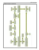
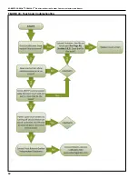
FIGURE 31: Burner troubleshooting in manual mode

Summary of Contents for CORAYVAC

Page 1: ...ent Installer Please take the time to read and understand these instructions prior to any installation Installer must give a copy of this manual to the owner Owner Keep this manual in a safe place in order to provide your service technician with necessary information Roberts Gordon LLC 1250 William Street P O Box 44 Buffalo New York 14240 0044 Telephone 1 716 852 4400 Fax 1 716 852 0854 Toll Free ...

Page 2: ......

Page 3: ... 10081500 Placement 21 3 11 Outside Air Supply P N 90707501K 21 SECTION 4 Typical Wiring Diagrams 23 SECTION 5 Communications 38 5 1 WebCTRL 38 5 2 BACnet IP Connection 38 5 3 Integration into Building Management System BMS 39 5 4 Communications Between Multiple CORAYVAC Modulating Heating Controls 40 5 5 Setting Baud Rate 41 5 6 Terminating Resistors 41 5 7 Control Board Setup 42 5 8 Touchscreen ...

Page 4: ......

Page 5: ...ee Page 4 Figure 2 through Page 5 Figure 4 1 3 California Proposition 65 In accordance with California Proposition 65 require ments a warning label must be placed in a highly visible location on the outside of the equipment i e near equipment s serial plate See label placement drawings on Page 4 Figure 2 through Page 5 Figure 3 for label location Avoid placing label on areas with extreme heat cold...

Page 6: ...ORDONRAY DF two stage unitary heater will not function with CORAYVAC or COMPLETE Modulating Heating Control 1 11 Control Board and Sensor Power The power supply for all sensors is from the 12 V terminal on the Rnet port of control board Power for the control board is 24 V provided by the transformer DANGER Electrical Shock Hazard Disconnect electric before service Controller must be properly groun...

Page 7: ...e used to control the infrared heating systems shown The layout consists of four zones of ROBERTS GORDON CORAYVAC Modu lating Heating Control FIGURE 1 Example Site Layout Zone 1 Zone 2 Zone 3 Zone 2 Sensor Zone 1 Sensor Zone 3 Sensor North Wall Outside Sensor Pump Zone 4 Sensor ROBERTS GORDON Modulating Heating Control and Variable Frequency Drive Zone 4 ...

Page 8: ... NO NC 11 14 12 COM NO NC 115V 230V 1 L1 L L2 N GND 120V 60HZ 1 20A L N GND FROM PS2 FROM PS1 CONTROL PWR IN TO PS 1 TO PS 2 120VAC 60HZ 15A 120VAC 60HZ 15A BLK WHT GRN BLK WHT GRN N G G N L L L L N N N N L1 L POWER INPUT POWER OUTPUT POWER INPUT POWER OUTPUT G CB1 VFD1 VFD2 Disconnect 30A L2 U1 V1 W1 U2 V2 W2 G G G L3 CB1 24Vac N1 Gnd TOUCH SCREEN 24V MS TP Gnd SENSOR A B C D S2 S1 MS TP N1 24Vac...

Page 9: ... Port E1 100 LAN LINK 8 7 6 5 See BAS Table Below Protocols 6 MS TP m MS TP s Off N2 On Lon SLTA Off BAUD 4 5 9600 Off Off 19 2 K Off On 38 4 K On Off 76 8 K On On On Modbus 8 Off Off On On Off 4 BACnet 3 7 Off On Off Off Off PTP Off Off On Access Port 2a Lon OptionOff On On 2 1 UO 1 UO 2 UO 3 UO 4 UO 8 UO 7 UO 6 UO 5 On Off 2 1 BAS Port BAS Port Settings Set Pot Full CW 24Vac DO NOT APPLY 24Vac T...

Page 10: ...s separate LonWorks card RS 485 Wiring Central Controller VFD s located inside CORAYVAC Modulating Heating Control Enclosure RS 485 Wiring BMS Operator s Workstation Outside Air Blower optional Repeater Outdoor Air Temperature Sensor Vacuum Pump Indoor Sensor one per zone CORAYVAC Burners Zone 1 Load Reactor as needed CORAYVAC Burners Zone 2 optional ...

Page 11: ... Indoor Sensor one per zone VANTAGE CTH3 Modulating Heaters VANTAGE CTH2V On Off Heaters NOTE Any combination of CORAYVAC VANTAGE CTH2V or VANTAGE CTH3 HEM heaters can be controlled from a central and or satellite controller Diagram above only shows one possible combination If combining a CORAYVAC system with VANTAGE CTH3 HEM unitary heaters on a single CORAYVAC Modulating Heating Control users ar...

Page 12: ... COMPLETE Modulating Heating Control Installation Manual P N 1006101NA CORAYVAC Modulating Heating Control Controller with Modem Installed Mounting Template P N 91702810 VFD Manual CORAYVAC Modulating Heating Control Controller with Modem Installed Installation Manual P N 1006101NA Mounting Template P N 91702810 VFD Manual COMPLETE Modulating Heating Control Installation Manual P N 1006101NA VFD M...

Page 13: ...epeater optional Supplied w 24 VAC transformer inside NEMA 1 enclosure P N 10060156 Indoor Sensor P N 10061003 Load Reactor P N 10061019 P N 10061020 P N 10061021 P N 10061022 LonWorks Card P N 10060160 USB L Cable P N 10061017 Terminating Resistor BT485 P N 10061018 ...

Page 14: ...nfigurable for ARC156 or EIA 485 2 wire Built in support for BACnet MS TP or ARC156 N2 and Modbus Port 2a Configurable for EIA 232 or EIA 485 2 wire or 4 wire Network protocol selectable for BACnet MS TP or PTP Modbus N2 LonWorks SLTA or modem Port 2b For LonWorks option Card Rnet port Interface with a BACview5 BACview6 RS sensors or local laptop and Equipment Touch Battery CR123A 10 yr life 720 c...

Page 15: ...int adjustment override button information screen diagnostics screen Outdoor Sensor P N 10081501 Dimensions W x H x D in 1 4 x 5 3 x 0 75 cm 3 6 x 13 5 x 1 9 Operating Temperature Range 40 to 221 F 40 to 105 C Enclosure NEMA 4 gasketed aluminum LB housing threaded connection 2 6 Touchscreen HMI Located on Central Controller Dimensions W x H x D in 5 4 x 4 6 x 1 3 cm 13 7 x 11 7 x 3 3 Power 24 Vac ...

Page 16: ...ce 10 Amps 2 2 2 HP 460V 3 Ø Drive used with EP 303 pump P N 10061205 Power Input 460 V 3 Ø 50 60 Hz Input Voltage Tolerance 10 Amps 4 1 1 HP 208 230V 3 Ø Drive used with EP 203 pump P N 10061206 Power Input 208 230 V 3 Ø 50 60 Hz Input Voltage Tolerance 10 Amps 4 3 2 HP 208 230V 3 Ø Drive used with EP 303 pump P N 10061207 Power Input 208 230 V 3 Ø 50 60 Hz Input Voltage Tolerance 10 Amps 7 ...

Page 17: ... layout for the project that clearly identifies the separate zones and wiring distances between all components 3 1 2 Familiarize yourself with the Controller and Vari able Frequency Drive component names and loca tions See Page 14 Figure 6 Figure 6 Note The VFD is located inside of the CORAYVAC Modulating Heating Control panel Be sure to plan accordingly DANGER Electrical Shock Hazard Disconnect e...

Page 18: ... Tx Rx n c EIA 232 DCD Rx Tx DTR Signal Ground BACnet Over ARCNET156 KBaud Made in USA Port 2a BT485 Port 1 Port 1 BT485 Conductors 2A 50 60 Hz Blinking Dot Run On Off Enhanced 8 7 6 5 4 3 2 1 8 7 6 5 4 3 2 1 IP Addr Assigned Default 10 100 BaseT Ethernet Port E1 100 LAN LINK 8 7 6 5 See BAS Table Below Protocols 6 MS TP m MS TP s Off N2 On Lon SLTA Off BAUD 4 5 9600 Off Off 19 2 K Off On 38 4 K O...

Page 19: ... damage from possible condensation leaks do not mount controller directly beneath pump Avoid install ing the controller in mezzanines direct sunlight or near external heat sources because these locations usually have unpredictable temperature rises FIGURE 7 Controller Mounting CORAYVAC Modulating Heating Control Dimensions shown in inches FIGURE 8 Controller Mounting COMPLETE Modulating Heating Co...

Page 20: ...ectrical Code local ordinances and any special diagrams furnished Canada Refer to Canadian Electrical Code CSA C22 1 Part 1 latest revision Plan accordingly 3 4 1 Switchable Loads The controller relays are rated for switching loads no greater than 6 A The total added current load for all 4 relays must not exceed 20 A 3 4 2 Control Programming Details Controllers are pre programmed Can be configure...

Page 21: ...id configuration FIGURE 9 Daisy Chain Network Configuration Cable Shielded cable One twisted pair of 18 AWG minimum or equivalent Belden 8451 1503A General Cable C2514 Wire Material PVC insulated parallel bonded Type 2 100 ohm platinum uses FT 4 Operating Temperature Range 40 to 105 C 40 to 221 F T C C C C C C C C C C T T R C C C C C C C C C C C T T R C C C C C C C C C C C C T C Segment Segment Se...

Page 22: ...num Mylar shield with 24 AWG 7x32 TC drain wire Jacket SmokeGard SmokeGard PVC 0 021 in 0 5334 mm wall 0 175 in 4 445 mm O D Halar E CTFE 0 010 in 0 254 mm wall 0 144 in 3 6576 mm O D DC Resistance 15 2 Ohms 1000 50 Ohms km nominal Capacitance 12 5 pF ft 41 pF meter nominal conductor to conductor Characteristic Impedance 100 Ohms nominal Weight 12 lb 1000 17 9 kg km UL Temperature Rating SmokeGard...

Page 23: ... distance required is greater The VFD will be energized via a Modbus command from the control board VFD Wire Size 1 HP 120V 12 AWG 1 HP 230V 1ph 12 AWG 1 HP 230V 3ph 12 AWG 1 HP 230V 1ph 12 AWG 1 HP 230V 3ph 12 AWG 1 HP 460V 3ph 12 AWG 2 HP 460V 3ph 12 AWG Description Single twisted pair low capacitance 12pF CL2P 22 AWG 7x30 TC foam FEP plenum rated cable Conductor 22 AWG 7x30 stranded copper tin ...

Page 24: ...ace It is important that the sensor is located in an area within the heated zone at occu pant level For the most accurate results sensors should be mounted on an inside wall away from any air vents or other sources of heat and cold In order to avoid short system cycles and inaccurate tempera ture readings do not mount sensors under the first section of radiant tube first 10 3 m section of tube aft...

Page 25: ...sor with the sensor module facing down to prevent accumulation of dirt or water 3 11 Outside Air Supply P N 90707501K If an outside air O A blower is to be used modifica tions to the outside air blower out of box wiring must be made to properly time and safety check the blower with the main pump See Page 28 Figure 15 and Page 34 Figure 18 for external wiring details Remove the internal connection ...

Page 26: ...ROBERTS GORDON CORAYVAC MODULATING HEATING CONTROL CONTROLLER INSTALLATION MANUAL 22 THIS PAGE LEFT INTENTIONALLY BLANK ...

Page 27: ...atest revision Wiring must conform to the most current National Electrical Code local ordinances and any special diagrams furnished Canada Refer to Cana dian Electrical Code CSA C22 1 Part 1 latest revi sion DANGER Electrical Shock Hazard Disconnect electric before service Controller must be properly grounded to an electrical source Failure to follow these instructions can result in death or elect...

Page 28: ...0 60 Hz Blinking Dot Run On Off Enhanced 8 7 6 5 4 3 2 1 8 7 6 5 4 3 2 1 IP Addr Assigned Default 10 100 BaseT Ethernet Port E1 100 LAN LINK 8 7 6 5 See BAS Table Below Protocols 6 MS TP m MS TP s Off N2 On Lon SLTA Off BAUD 4 5 9600 Off Off 19 2 K Off On 38 4 K On Off 76 8 K On On On Modbus 8 Off Off On On Off 4 BACnet 3 7 Off On Off Off Off PTP Off Off On Access Port 2a Lon OptionOff On On 2 1 U...

Page 29: ...connect 30A L2 U1 V1 W1 U2 V2 W2 G G G L3 CB1 24Vac N1 Gnd P1 P2 Z1 Z2 Z3 Z4 TRANSFORMER 24Vac 24Vac N1 L2 N L3 L1 L L2 N L3 L1 L 115V 230V 1O L2 N GND 3 10 U OK OK VFD1 OUT VFD2 OUT VFD2 OPTIONAL Single pole circuit breaker for 115V OA Blower 1 OA Blower 2 OA Blowers 4 5 6 7 8 9 2 1 11 3 10 4 5 6 7 8 9 2 1 11 V W U V W VFD PWR IN L1 TERMINAL BLOCK 2 Indicator Lights Optional BLK WHT GRN ...

Page 30: ...A 50 60 Hz Blinking Dot Run On Off Enhanced 8 7 6 5 4 3 2 1 8 7 6 5 4 3 2 1 IP Addr Assigned Default 10 100 BaseT Ethernet Port E1 100 LAN LINK 8 7 6 5 See BAS Table Below Protocols 6 MS TP m MS TP s Off N2 On Lon SLTA Off BAUD 4 5 9600 Off Off 19 2 K Off On 38 4 K On Off 76 8 K On On On Modbus 8 Off Off On On Off 4 BACnet 3 7 Off On Off Off Off PTP Off Off On Access Port 2a Lon OptionOff On On 2 ...

Page 31: ...UT CB1 VFD1 VFD2 Disconnect 30A L2 U1 V1 W1 U2 V2 W2 G G G L3 24Vac N1 Gnd P1 P2 Z1 Z2 Z3 Z4 TRANSFORMER 24Vac 24Vac N1 L2 N L3 L1 L L2 N L3 L1 L 115V 230V 1O L2 N GND 3 10 U OK OK VFD1 OUT VFD2 OUT VFD2 OPTIONAL OA Blower 1 OA Blower 2 OA Blowers 4 5 6 7 8 9 2 1 11 3 10 4 5 6 7 8 9 2 1 11 V W U V W VFD PWR IN L1 TERMINAL BLOCK 2 Indicator Lights Optional BLK WHT GRN ...

Page 32: ...e Copper 24Vac 50VA Without Keypad 26Vdc 23W 0 9A Outputs 24Vdc Max 50mA Max Format Pot 2 wire 4 wire 2 wire4 wire Rx Net Net n c Tx Tx Rx n c EIA 232 DCD Rx Tx DTR Signal Ground BACnet Over ARCNET156 KBaud Made in USA Port 2a BT485 Port 1 Port 1 BT485 Conductors 2A 50 60 Hz Blinking Dot Run On Off Enhanced 8 7 6 5 4 3 2 1 8 7 6 5 4 3 2 1 IP Addr Assigned Default 10 100 BaseT Ethernet Port E1 100 ...

Page 33: ...120VAC 60HZ 15A 230V 460V 3O L1 L2 GND L3 N G G N L L L L N N N N G N1 24Vac N1 24Vac RELAY 3 RELAY 2 RELAY 1 RELAY 5 RELAY 6 RELAY 4 24Vac 24Vac N1 Zone 1 Burners Zone 2 Burners Zone 3 Burners Zone 4 Burners Pump Operated Zones G N L G N L G N L G N L CB2 20A 11 14 12 COM NO NC 11 14 12 COM NO NC A1 A2 TERMINAL BLOCK 1 11 14 12 COM NO NC A1 A2 11 14 12 COM NO NC A1 A2 11 14 12 COM NO NC A1 A2 11 ...

Page 34: ...e Copper 24Vac 50VA Without Keypad 26Vdc 23W 0 9A Outputs 24Vdc Max 50mA Max Format Pot 2 wire 4 wire 2 wire4 wire Rx Net Net n c Tx Tx Rx n c EIA 232 DCD Rx Tx DTR Signal Ground BACnet Over ARCNET156 KBaud Made in USA Port 2a BT485 Port 1 Port 1 BT485 Conductors 2A 50 60 Hz Blinking Dot Run On Off Enhanced 8 7 6 5 4 3 2 1 8 7 6 5 4 3 2 1 IP Addr Assigned Default 10 100 BaseT Ethernet Port E1 100 ...

Page 35: ...GND 120VAC 60HZ 15A 120VAC 60HZ 15A BLK WHT GRN N G G N L L L L N N N N G N1 24Vac N1 24Vac RELAY 3 RELAY 2 RELAY 1 RELAY 5 RELAY 6 RELAY 4 24Vac 24Vac N1 Zone 1 Burners Zone 2 Burners Zone 3 Burners Zone 4 Burners Pump Operated Zones G N L G N L G N L G N L CB2 20A 11 14 12 COM NO NC 11 14 12 COM NO NC A1 A2 TERMINAL BLOCK 1 11 14 12 COM NO NC A1 A2 11 14 12 COM NO NC A1 A2 11 14 12 COM NO NC A1 ...

Page 36: ... 24Vac 50VA Without Keypad 26Vdc 23W 0 9A Outputs 24Vdc Max 50mA Max Format Pot 2 wire 4 wire 2 wire4 wire Rx Net Net n c Tx Tx Rx n c EIA 232 DCD Rx Tx DTR Signal Ground BACnet Over ARCNET156 KBaud Made in USA Port 2a BT485 Port 1 Port 1 BT485 Conductors 2A 50 60 Hz Blinking Dot Run On Off Enhanced 8 7 6 5 4 3 2 1 8 7 6 5 4 3 2 1 IP Addr Assigned Default 10 100 BaseT Ethernet Port E1 100 LAN LINK...

Page 37: ...12 COM NO NC A1 A2 TERMINAL BLOCK 1 BLK WHT GRN L 120V 60HZ 1O 20A N GND ZONE 4 TO ADDITIONAL BURNERS L N G CTH3 R W FIRE OUT ANALOG IN 120VAC 60HZ 5A L N G CTH3 R W FIRE OUT FIRE IN 120VAC 60HZ 5A ZONE 3 L N G CTH3 R W FIRE OUT ANALOG IN 120VAC 60HZ 5A L N G CTH3 R W FIRE OUT FIRE IN 120VAC 60HZ 5A TO ADDITIONAL BURNERS ZONE 1 L N G BURNER ZONE 2 LOW VOLTAGE THERMOSTAT L N G BURNER LOW VOLTAGE TH...

Page 38: ...23W 0 9A Outputs 24Vdc Max 50mA Max Format Pot 2 wire 4 wire 2 wire4 wire Rx Net Net n c Tx Tx Rx n c EIA 232 DCD Rx Tx DTR Signal Ground BACnet Over ARCNET156 KBaud Made in USA Port 2a BT485 Port 1 Port 1 BT485 Conductors 2A 50 60 Hz Blinking Dot Run On Off Enhanced 8 7 6 5 4 3 2 1 8 7 6 5 4 3 2 1 IP Addr Assigned Default 10 100 BaseT Ethernet Port E1 100 LAN LINK 8 7 6 5 See BAS Table Below Prot...

Page 39: ... Z2 Z3 Z4 P1 P2 24Vac N1 Gnd TRANSFORMER N N L G N L G N L G N L RELAY 7 RELAY 8 L Outside Air Blower 1 Outside Air Blower 2 N M L N M T1 T2 T3 T1 T2 T3 G N L G N L G N L G N L CB2 20A 11 14 12 COM NO NC A1 A2 11 14 12 COM NO NC A1 A2 11 14 12 COM NO NC A1 A2 11 14 12 COM NO NC A1 A2 TERMINAL BLOCK 1 11 14 12 COM NO NC A1 A2 11 14 12 COM NO NC A1 A2 11 14 12 COM NO NC A1 A2 11 14 12 COM NO NC A1 A...

Page 40: ...56 Port 2a Rnet Gnd Rnet Rnet 12V Xnet Xnet Gnd Xnet Expansion Local Rnet Gnd Sense 12V Rnet Access EIA 485 EIA 232 Thermistor dry contact Mode Select Universal Input mA RTD Volts 10V Max 20mA Max Inputs All UI 4 UI 3 UI 2 UI 1 Gnd Gnd Gnd Gnd 8 7 6 5 4 3 2 1 UI 8 Gnd UI 6 UI 7 UI 5 Gnd Gnd Gnd UI 12 UI 11 UI 10 UI 9 Gnd Gnd Gnd Gnd 24 Vdc 24 Vdc 200mA maximum Auto Off On 0 20mA 0 10Vdc Relay Cont...

Page 41: ...atelaite 1 Satelaite 2 120 Vac HOT NEUTRAL GND REP 485 ON OFF BT 485 CONNECTOR ERTH GROUND POWER CONNECTOR NETWORK B NETWORK B POWER JUMPER CONNECTOR BT 485 CONNECTOR NETWORK A CONNECTOR NETWORK A LED1 LED2 24 Vac LINE LOAD 3 1 4 5 Shield 0 8 Amps Fuse To next Controller L1 L2 120 vac Shield LED3 120V 60HZ 1 3 24V 20VA 4 5 TRANSFORMER Terminal Block GND BASE PLATE GREEN BLACK BLACK WHITE BLUE YELL...

Page 42: ...djusting setpoints and other control properties Graphically trending building conditions Viewing and acknowledging alarms Custom alarm management capabilities to allow notifications via e mail text messaging etc for situations such as when zone temperatures drop below setpoints or exceed user defined require ments Graphical representation of system s status A WebCTRL license is issued and software...

Page 43: ... cycled to the control board To properly cycle power to the control board and touch screen turn the circuit breaker located on the termi nal strip above the control board off for 10 seconds before turning it back on To use the default IP address ensure DIP switch 2 is in the off position Custom IP Address Assign a custom IP address using the touchscreen located on the central control panel provide...

Page 44: ...he MS TP Port 1 terminal on controller 2 and so on in a daisy chain Page 38 Section 5 fashion Shield wires for MS TP cables should be twisted together but not grounded at all satellite controllers in daisy chain Ground shield wire at central panel only Maximum of 31 controllers to 1 central controller For communication cable requirements See Page 16 Section 3 4 2 A MAC address is required for each...

Page 45: ...1 BAS Port BAS Port Settings Set Pot Full CW 24Vac DO NOT APPLY 24Vac TO UNIVERSAL OUTPUTS External 24Vdc relay coil only 3 UO 2 UO 1 2 1 UO 4 UO 3 6 5 4 7 8 6 UO 7 UO 6 UO 5 3 1 2 4 5 UO 8 7 8 Gnd Gnd Gnd Gnd Gnd Gnd Gnd Gnd Aux Power Out Port 2b Port 2a IOPro812u 07 10 12 Rev 6 Open Energy Management Equipment 26Vdc I O Pro 812u CONTROLLER Rotary Switches Range 1 99 Archive Valid Port 2a Rx Port...

Page 46: ...d Jumper setting on I O Pro controller HOA Switches set to AUTO Universal Output jumpers for UO 1 UO 2 UO 3 and UO 4 set to RELAY Jumpers for UO 5 UO 6 UO7 and UO 8 set to 0 10v Universal input jumpers for UI 1 UI 2 and UI 3 set to Thermistor dry contact RTD UI 4 and UI 5 can be optionally used for manual pump operation Port 1 jumpers set to 485 Port 2a jumpers configured for EIA485 2 WIRES The CO...

Page 47: ...oller s memory is full In the WebCTRL for OEMs application reduce the amount of trend data being stored in the controller In SiteBuilder reduce the amount of control programs 3 A setup error Verify The address has been set on the rotary switches See Addressing the controller on Page 39 The address is unique on the network DIP switches are set correctly 4 A system error Obtain a Module Status Repor...

Page 48: ... rate for Port 1 is set using switches 4 5 It is important to note that the maxi mum communication distance achievable before a REPEATER is necessary is dependent on the baud rate A maximum baud rate of 19 2K can be used for distances up to 4000 1219 m If the maximum baud rate of the Port is used 76 8K a REPEATER is required after 2000 609 m or 31 controllers which ever comes first Set switch 4 to...

Page 49: ...that the system s are properly installed and that all universal inputs and outputs ports rotary and DIP switches are properly config ured for the system s From the System View screen press Setup The administrator password screen will appear prompting users to login Login for setup case sensitive Username Admin Password admin To Home Screen To Alarm Manager Screen To Previous Screen To Screens Spec...

Page 50: ...e list It will take you to the local Home screen for that controller Optional Users have the option to set any controller on the network as the Home screen To do so from the System View screen select Setup then Touchscreen Setup and then Home Screen Setup Check the box for use equipment standby home screen then select a desired panel for the Home screen 5 8 2 To update the System Touch s firmware ...

Page 51: ...Figure 9 through Page 18 Figure 10 If the MS TP communications wire length is above 4000 1219 m a repeater must be used to extend the signal The repeater can also be used to install in different meth ods To extend communications beyond the standard 4000 1219 m limitation See Page 30 Figure 16 To add parallel branches of ROBERTS GOR DON CORAYVAC Modulating Heating Control communications bus wiring ...

Page 52: ...o enter the PROGRAM mode and access the Parameters hold OK until P01 appears Display reads P01 6 1 2 Unlock Parameter Higher than P14 Use the arrow buttons to scroll to P14 the factory set password is 0 0 Press OK to enter password 101 This unlocks parameters higher than P14 6 1 3 Scroll Up or Down Use the arrow buttons to scroll to the desired param eter number For new parameter settings See Page...

Page 53: ...uency according to Page 57 Step 7 1 1 and input P02 Minimum Frequency Hz 0 0 40 0 After setting the system take right Fre quency according the to Page 57 Step 7 1 3 and input P03 Accelerated Time sec 5 10 P04 Decelerated Time sec 5 10 P07 Nominal Motor Voltage V 230 Rated Motor Voltage from motor data plate P08 Rated Motor Current A 4 8 Rated Motor Current from motor data plate P09 Rated Motor Fre...

Page 54: ...additional braking resistors in parallel Make sure to adhere to mini mum resistance values 03 0 I Overcurrent motor Overcurrent at output Motor overload Overtemperature at heat sink Short circuit ground fault Motor with constant speed Determine the overload or fault Motor starts The load stalled or has seized Check whether there is a star delta motor wir ing error Motor accelerates decelerates The...

Page 55: ...ture frost Excessively low heat sink temperature The variable frequency drive will be switched off if the ambient air temperature is lower than 14 F 10 C Raise the temperature over 14 F 10 C in order to start the variable frequency drive 0A P dEF Parameter default The parameter s default setting has been loaded Press the STOP button The DC Variable frequency drive is ready for an application spe c...

Page 56: ...ut for one hour or until manual reset Note Burners in zone may not all fire at exact same time Ignition of all burners in zone may vary 3 5 seconds 4 Vacuum pump will run at 100 speed for 2 min utes from time that initial Run command is issued 5 Modulation period begins after 2 minute initial run period CORAYVAC Modulating Heating Control compares outdoor air temperature with zone tem perature set...

Page 57: ...en and flame is established If flame is detected by burner flame sensor burner gas valve remains open If flame is not established burner ignition sequence will repeat After three trials the burner module will lockout for one hour or until manual reset Note Burners in zone may not all fire at exact same time Ignition of all burners in zone may vary 3 5 seconds 3 When flame is established burner wil...

Page 58: ...as designed 5 When the call for heat is satisfied burners shut off zone LED light on control panel turns off 6 The pump will continue operation for a post purge period of 2 minutes 7 After the post purge period vacuum pump and vacuum pump LED simultaneously turn off OPTION If outside air blower is installed blower will turn off after post purge period ...

Page 59: ...n is 60 0 If it is lower than 60 0 hit the up arrow button on the VFD until the number reads 60 0 Let the burn ers fire for approximately 20 30 minutes to warm up the system Using a manometer check the end vent vacuum in each zone each branch of burners See Page 56 Figure 24 If the lowest end vent vacuum reading is above 3 0 w c reduce the vacuum pump speed Generally the lowest end vent vacuum rea...

Page 60: ...uring vacuum pressure at end burner furthest away from vacuum pump All other end burners on the other branches should have the same vacuum pressure reading The vacuum pressure on end burners closer to the vacuum pump are set by adjusting the damper on the damper coupling for each branch See Page 57 Figure 25 for possible locations of damper couplings ...

Page 61: ... Damper Coupling Damper NOTE Damper setting will vary Zone 1 Zone 2 Zone 3 Zone 1 End Vent Zone 3 End Vent Zone 2 End Vent Zone 1 Damper Coupling Zone 2 Damper Coupling Zone 3 Damper Coupling Pump Damper Description Part Number Damper Coupling 4 10 cm 01331900 Damper Coupling 6 15 cm E0009356 ...

Page 62: ... This overlaps the startup procedure programmed into the VANTAGE Modulating burner After this the VAN TAGE Modulating burner will modulate accordingly Post purge operations are also programmed directly into the VANTAGE Modulating burner See VAN TAGE Modulating VANTAGE HEM installation and operation manuals P N 134100NA 139100NA for further details For CORAYVAC systems an initial 100 heat command i...

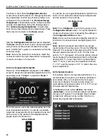
Page 63: ...The Configurations Service screen is used to adjust how many zones vacuum pumps and the type of heating system that is connected to the con troller you are programming Select the box next to Number of Zones and set the number of zones connected to that controller Select the box next to each Zone Selection and choose the type of heating system that is associated with that zone Example 1 If the cont...

Page 64: ...re dis played next to the flame icon Arrow Buttons To override an unoccupied temperature select the on button icon to select the desired space temperature and the duration of the override On Button Icon Note The Configure icon will bring users to the Configuration Zones screen It is recommended to create all schedules prior to adjusting the settings in the Configuration Zones screen Note Allow a f...

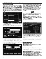
Page 65: ... Weekly Continuous Select Weekly to create a complete 7 day schedule Note Dated will allow users to set a specific time and date for the system to be active The date can be set to a single day or a specific day each month or each year Continuous will allow users to select a start time and date and end time and date for the system to be active continuously For Priority select Normal to create an oc...

Page 66: ...ule select all week days and select All Day Event for the start and end times Press the arrows to navigate between multiple schedules Note If multiple Normal schedules were created this is where information for all schedules can be viewed Users can delete the schedule period by selecting Delete Period or delete all schedules in the zone by selecting Delete All Press Save when complete 8 7 Zone Con...

Page 67: ...8 9 Alarms Alarm screen can be accessed from the alarm bell on home screen or through the MENU Use this screen to see which alarms are active if any Use the info button for more information about the alarm The red exclamation point on home screen is an alarm history NOT necessarily active alarms 8 10 Alarm Configuration The preconfigured alarm times in this screen should not be changed The Vacuum ...

Page 68: ...uest is satisfied the Post Purge timer runs the pump for an additional 2 minutes The Minimum Off timer prevents the system from accidentally tripping an APS alarm if it cycles OFF and back ON too quickly The Run Burner 1 at 100 timer is for Unitary Modulating heaters It runs the units at 100 for 180 seconds at startup Next is an override feature for the Outside Air Temperature Override the tempera...

Page 69: ...SECTION 8 PROGRAMMING AND TROUBLESHOOTING THE SYSTEM 65 THIS PAGE LEFT INTENTIONALLY BLANK ...

Page 70: ...t distributor or Roberts Gordon LLC Inside Sales at 716 852 4400 Table of Contents Page 67 Figure 26 Vacuum pump does not turn on Page 68 Figure 27 VFD Turns on but the desired zone does not turn on Page 69 Figure 28 VFD showing a fault sign Page 69 Figure 29 VFD input power issue Page 70 Figure 30 Vacuum pump power issue Page 71 Figure 31 Burner troubleshooting in man ual mode Page 72 Figure 32 A...

Page 71: ...SECTION 9 TROUBLESHOOTING 67 FIGURE 26 Vacuum pump does not turn on ...

Page 72: ...ROBERTS GORDON CORAYVAC MODULATING HEATING CONTROL CONTROLLER INSTALLATION MANUAL 68 FIGURE 27 VFD Turns on but the desired zone does not turn on ...

Page 73: ...SECTION 9 TROUBLESHOOTING 69 FIGURE 28 VFD showing a fault sign FIGURE 29 VFD input power issue ...

Page 74: ...ROBERTS GORDON CORAYVAC MODULATING HEATING CONTROL CONTROLLER INSTALLATION MANUAL 70 FIGURE 30 Vacuum pump power issue ...

Page 75: ...SECTION 9 TROUBLESHOOTING 71 FIGURE 31 Burner troubleshooting in manual mode ...

Page 76: ...ROBERTS GORDON CORAYVAC MODULATING HEATING CONTROL CONTROLLER INSTALLATION MANUAL 72 FIGURE 32 After 45 second prepurge burners do not light ...

Page 77: ...SECTION 9 TROUBLESHOOTING 73 After 45 second prepurge burners do not light continued ...

Page 78: ...ROBERTS GORDON CORAYVAC MODULATING HEATING CONTROL CONTROLLER INSTALLATION MANUAL 74 FIGURE 33 Burner intermittent lockout ...

Page 79: ...SECTION 9 TROUBLESHOOTING 75 FIGURE 34 APS does not close within 60 seconds after VFD receives run command ...

Page 80: ...ROBERTS GORDON CORAYVAC MODULATING HEATING CONTROL CONTROLLER INSTALLATION MANUAL 76 FIGURE 35 Zone sensor issue ...

Page 81: ...SECTION 9 TROUBLESHOOTING 77 FIGURE 36 Air Pressure Switch alarm ...

Page 82: ...ROBERTS GORDON CORAYVAC MODULATING HEATING CONTROL CONTROLLER INSTALLATION MANUAL 78 FIGURE 37 Modbus troubleshooting ...

Page 83: ...SECTION 9 TROUBLESHOOTING 79 FIGURE 38 Repeater troubleshooting ...

Page 84: ...ROBERTS GORDON CORAYVAC MODULATING HEATING CONTROL CONTROLLER INSTALLATION MANUAL 80 FIGURE 39 BACnet MS TP troubleshooting ...

Page 85: ...SECTION 9 TROUBLESHOOTING 81 BACnet MS TP troubleshooting continued ...

Page 86: ...ROBERTS GORDON CORAYVAC MODULATING HEATING CONTROL CONTROLLER INSTALLATION MANUAL 82 FIGURE 40 Touch pad troubleshooting ...

Page 87: ...er s installed if required Resistor s installed if required Are sensors installed in proper location Is OAT sensor installed in proper location VFD programmed properly not manual mode All additionally required BMS hardwire installed Controller MAC addresses used are unique All dip switches set properly Matching touchscreen and dip switch baud rate settings Schedule is set Design temp setpoints are...

Page 88: ...e heater s current Installa tion Operation and Service manual to help ensure all safety systems are in working order before leaving the heater to operate Minor faults may be traced by using the troubleshooting charts Carbon Monoxide Hazard WARNING Use only genuine ROBERTS GORDON replacement parts per this installation operation and service manual Failure to follow these instructions can result in ...

Page 89: ... Batt External Battery Gnd 3V Status Module 3V Lithium Battery CR 123A 0 Download required 3 Comm setup error 1 Control Program Error 4 System error 8 Formatting 2 RAM full Chase OK Status Codes Class 2 ONLY Use Copper 24Vac 50VA Without Keypad 26Vdc 23W 0 9A Outputs 24Vdc Max 50mA Max Format Pot 2 wire 4 wire 2 wire4 wire Rx Net Net n c Tx Tx Rx n c EIA 232 DCD Rx Tx DTR Signal Ground BACnet Over...

Page 90: ...0 Download required 3 Comm setup error 1 Control Program Error 4 System error 8 Formatting 2 RAM full Chase OK Status Codes Class 2 ONLY Use Copper 24Vac 50VA Without Keypad 26Vdc 23W 0 9A Outputs 24Vdc Max 50mA Max Format Pot 2 wire 4 wire 2 wire4 wire Rx Net Net n c Tx Tx Rx n c EIA 232 DCD Rx Tx DTR Signal Ground BACnet Over ARCNET156 KBaud Made in USA Port 2a BT485 Port 1 Port 1 BT485 Conducto...

Page 91: ... 80300109 4 Fuse 0 8 A 91319910 5 Base Plate 10060154 REP 485 ON OFF BT 485 CONNECTOR ERTH GROUND REP 485 POWER CONNECTOR NETWORK B NETWORK B POWER JUMPER CONNECTOR BT 485 CONNECTOR NETWORK A CONNECTOR NETWORK A LED1 LED2 24 Vac LINE LOAD 3 1 4 5 Shield 0 8 Amps Fuse 1 2 Shield 2 1 3 2 1 1 2 3 LED3 120V 60HZ 1 3 24V 20VA 4 5 TRANSFORMER Terminal Block BASE PLATE GREEN BLACK BLACK WHITE BLUE YELLOW...

Page 92: ... switch Mark all wires connected to the VFD noting the ter minals to which they are secured Remove all wires from the VFD terminals Remove the VFD from its mounting plate by removing the four securing screws Verify that the input voltage noted on the rating plate of the VFD matches the input voltage of the old VFD Secure the new VFD to the mounting plate with the four screws Return all wires to th...

Page 93: ...mbedded networking technology well suited for real time control applications in both the industrial and commercial marketplaces Its robust performance and the availability of low cost silicone makes it the network of choice in BAS s ARC156 is a unique implementation of ARCnet ARC156 is similar to Master Slave Token Passing MS TP The main difference between them is speed ARC156 baud rate is 156 kbp...

Page 94: ...ut the DIAG485 s Bias jumper in place 5 Turn on power to control board 6 Set the correct network number to the unique BACnet ARC156 network at the site 7 Set a unique Device Instance number The most common communication problems result from not properly following the configuration steps outlined above Review all steps and use the following list to check your settings Verify accuracy of the followi...

Page 95: ...7 Set the Port 1 jumper to 485 setting Note A dedicated 24 AWG to 18 AWG twisted pair wire EIA 485 2000 610 m for 76 8 kbps 3000 914 4 m for 9600 bps 19 2 or 38 4 kbps before needing a Repeater Devices should be daisy chained and not star wired If the controller is at either end of a network seg ment connect a BT485 Terminating Resistor P N 10061018 to the I O Pro 812u Use the same polarity throug...

Page 96: ...twork at the touch screen 9 Set a unique Device Instance number NOTE The most common communication problems are the result of not properly following the configuration steps outlined Review steps and use the following list to check your settings Verify accuracy of the following Hardware settings for speaking BACnet MS TP Baud rate DIP switches 4 and 5 Protocol DIP switches 6 7 and 8 jumpers set to ...

Page 97: ... 36 Figure 19 3 Set the Selector DIP Switches 4 and 5 for the appropriate communications speed 9600 19 2k 38 4k or 76 8k bps 4 Set Comm Selector DIP Switch 3 to ON for Port 2 Note Comm Selector DIP Switch 4 Port 1 will be set by the manufacturer 5 Set the DIP Switch Selector 6 8 for BACnet PTP The following example shows the DIP Switches set for 38 4k Port 2 and BACnet PTP 6 Connect the communicat...

Page 98: ...ocol packets for carrying BACnet messages over wide area networks and the Internet This network layer offers the fastest speed and allows for communication of BACnet on the highest network layer Although the speed is very fast there is a lot of overhead required in this kind of network topology Overhead refers to information inside the data packet message being passed over the network requiring ex...

Page 99: ...ons Maximum cable length 328 100 m Use one of the following CAT5 or higher Ethernet cables o A cross over cable to connect the controller directly to the third party device o A straight through cable to connect the controller to a hub or switch and a second straight through cable to connect the hub or switch to the third party device Note Use the same polarity throughout the network segment 4 Turn...

Page 100: ...the fastest speed and allows for communication of BACnet on the highest network layer To set up the Modulating Controller for BACnet over Ethernet 1 Turn off power to control board Note The controller reads the address each time you turn it on 2 Set Comm Selector DIP Switches 1 through 8 OFF Note The default address is an intranet address Data packets from this address are not routable to the Inte...

Page 101: ... 12 6 Modbus The Modbus protocol is used mostly in the industrial process market to communicate between PLCs Pro grammable Logic Controllers Modbus is not a protocol that is particularly well suited for building management because of its limited master slave structure However many companies offer Modbus as an open protocol solution because it is relatively easy to construct an interface 12 6 1 To ...

Page 102: ...61018 to the I O Pro 812u Note Use the same polarity throughout the network segment 7 Turn on power to control board 12 6 2 To set up the Modulating Controller for Modbus RTU or ASCII on Port 2a 1 Turn off power to control board 2 Using the rotary switches set the controller s address Set the Tens 10 s switch to the tens digit of the address and set the Ones 1 s switch to the ones digit 3 Set the ...

Page 103: ... kbps 3000 914 4 m for 9600 bps 19 2 or 38 4 kbps before needing a Repeater Devices should be daisy chained and not star wired If the controller is at either end of a network seg ment connect a terminating resistor P N 10061018 to the I O Pro 812u Note Use the same polarity throughout the network segment EIA 232 2 wire Connect to Tx Rx DTR DCD and Gnd using three wire termination with pins 3 and 4...

Page 104: ...jumpers upon power up 12 6 3 To set up the Modulating Controller for Modbus over IP 1 Turn off power to control board 2 Check the communications wiring for shorts and grounds 3 Connect Port E1 to the third party device Note Port E1 will still be capable of BACnet communication Wiring Specifications Maximum wire length 328 100 m Use one of the following CAT5 or higher Ethernet cables o A cross over...

Page 105: ... 2000 610 m for 76 8 kbps 3000 914 4 m for 9600 bps 19 2 or 38 4 kbps before needing a Repeater Devices should be daisy chained and not star wired If the controller is at either end of a network seg ment connect a terminating resistor P N 10061018 to the I O Pro 812u NOTE Use the same polarity throughout the network segment 7 Turn on power to control board To set up the Modulating Controller for N...

Page 106: ...ss switches 1 99 If control lers have duplicate addresses network communi cation can be lost NOTES If RX LED is solid then the terminations are incor rect If the network has greater than 32 devices or exceeds 2 000 609 6 m a Repeater should be installed If a controller begins or ends a network segment a terminating resistor may be needed The controller recognizes physical changes DIP switches rota...

Page 107: ...olarity insensitive Use 24 to 16 AWG twisted pair wire 6 Turn on power to control board Verify accuracy of the following Baud rate DIP switches 1 and 2 set to 38 4 kbps Protocol DIP switches 6 7 and 8 Jumper set to EIA 485 2 wire when using the Lon Works Option Card Proper connection wiring Unique rotary address switches 1 99 If controllers have duplicate addresses network communication can be los...

Page 108: ... Unit Page 107 Figure 47 Alarms Page 107 Figure 48 VFD Status Page 108 Figure 49 Configuration Service Page 108 Figure 50 Configuration Zones Page 109 Figure 51 Configuration Unit Page 109 Figure 52 Configuration Alarm Page 110 Figure 53 Hardware I O Page 110 Figure 54 Touchscreen System Page 111 Figure 55 Touchscreen Setup Page 111 Figure 56 Trends Page 112 Figure 57 Communication Page 112 Figure...

Page 109: ...SECTION 13 TOUCHSCREEN TREE 105 Touchscreen Tree Overview continued ...

Page 110: ...ROBERTS GORDON CORAYVAC MODULATING HEATING CONTROL CONTROLLER INSTALLATION MANUAL 106 FIGURE 45 System Status FIGURE 46 Schedules ...

Page 111: ...SECTION 13 TOUCHSCREEN TREE 107 FIGURE 47 Maintenance Unit FIGURE 48 Alarms ...

Page 112: ...ROBERTS GORDON CORAYVAC MODULATING HEATING CONTROL CONTROLLER INSTALLATION MANUAL 108 FIGURE 49 VFD Status FIGURE 50 Configuration Service ...

Page 113: ...SECTION 13 TOUCHSCREEN TREE 109 FIGURE 51 Configuration Zones FIGURE 52 Configuration Unit ...

Page 114: ...DON CORAYVAC MODULATING HEATING CONTROL CONTROLLER INSTALLATION MANUAL 110 FIGURE 53 Configuration Alarm FIGURE 54 Hardware I O Note Settings in Hardware I O screen are factory defaults and SHOULD NOT BE ADJUSTED ...

Page 115: ...SECTION 13 TOUCHSCREEN TREE 111 FIGURE 55 Touchscreen System FIGURE 56 Touchscreen Setup ...

Page 116: ...ROBERTS GORDON CORAYVAC MODULATING HEATING CONTROL CONTROLLER INSTALLATION MANUAL 112 FIGURE 57 Trends FIGURE 58 Communication FIGURE 59 IP ...

Page 117: ...cian qualified in the installation and service of control systems for heating equipment You cannot prove original purchase date and required annual maintenance history The data plate and or serial number are removed defaced modified or altered in any way The ownership of the ROBERTS GORDON CORAYVAC COMPLETE Modulating Heating Control is moved or transferred This warranty is nontransferable Roberts...

Page 118: ...ROBERTS GORDON CORAYVAC MODULATING HEATING CONTROL CONTROLLER INSTALLATION MANUAL 114 ...

Page 119: ...SECTION 14 THE ROBERTS GORDON CORAYVAC COMPLETE MODULATING HEATING CONTROL LIMITED WARRANTY 115 ...

Reviews: