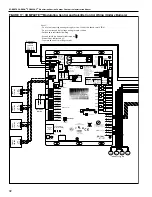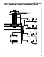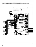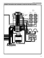
ROBERTS GORDON
®
CORAYVAC
®
M
ODULATING
H
EATING
C
ONTROL
C
ONTROLLER
I
NSTALLATION
M
ANUAL
44
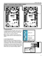
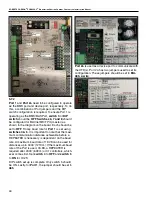
5.7.2
Port 1
and
Port 2a
need to be configured to operate
as the BMS port and device port, respectively. To do
this, a combination of Port jumpers and the DIP
switch configuration is required. To ensure Port 1 is
operating as the BMS/BAS Port,
switch 3
of
DIP
switch
should be
OFF
.
Switches 6, 7 and 8
should
be configured for BACnet MS/TP m(master) as
shown in the diagram on the board. Each should be
set to
OFF
. Finally, baud rate for
Port 1
is set using
switches 4 & 5
. It is important to note that the maxi-
mum communication distance achievable before a
REPEATER is necessary is dependent on the baud
rate. A maximum baud rate of 19.2K can be used for
distances up to 4000’ (1219 m). If the maximum baud
rate of the Port is used, 76.8K, a REPEATER is
required after 2000’ (609 m) or 31 controllers, which-
ever comes first. Set
switch 4
to
OFF
and
switch 5
to
ON
for 19.2K.
DIP switch set up is complete. Only switch 5 should
be ON. Lastly, for
Port 1
, the jumper should be set to
485
.
Port 2a
is used as a device port to communicate with
the VFD(s). Port 2a has two jumpers used to set its
configuration. These jumpers should be set to
EIA-
485, 2-wire
.
Summary of Contents for CORAYVAC
Page 2: ......
Page 4: ......
Page 69: ...SECTION 8 PROGRAMMING AND TROUBLESHOOTING THE SYSTEM 65 THIS PAGE LEFT INTENTIONALLY BLANK ...
Page 71: ...SECTION 9 TROUBLESHOOTING 67 FIGURE 26 Vacuum pump does not turn on ...
Page 75: ...SECTION 9 TROUBLESHOOTING 71 FIGURE 31 Burner troubleshooting in manual mode ...
Page 77: ...SECTION 9 TROUBLESHOOTING 73 After 45 second prepurge burners do not light continued ...
Page 81: ...SECTION 9 TROUBLESHOOTING 77 FIGURE 36 Air Pressure Switch alarm ...
Page 83: ...SECTION 9 TROUBLESHOOTING 79 FIGURE 38 Repeater troubleshooting ...
Page 85: ...SECTION 9 TROUBLESHOOTING 81 BACnet MS TP troubleshooting continued ...
Page 109: ...SECTION 13 TOUCHSCREEN TREE 105 Touchscreen Tree Overview continued ...
Page 111: ...SECTION 13 TOUCHSCREEN TREE 107 FIGURE 47 Maintenance Unit FIGURE 48 Alarms ...
Page 113: ...SECTION 13 TOUCHSCREEN TREE 109 FIGURE 51 Configuration Zones FIGURE 52 Configuration Unit ...
Page 115: ...SECTION 13 TOUCHSCREEN TREE 111 FIGURE 55 Touchscreen System FIGURE 56 Touchscreen Setup ...
Page 118: ...ROBERTS GORDON CORAYVAC MODULATING HEATING CONTROL CONTROLLER INSTALLATION MANUAL 114 ...


