SECTION 7: V
ENTING
13 of 57
terminals.
See Page 16, Figure 10
. As an option, the
vent and air intake are r
u
n as separate pipes to a
concentric vent box and a concentric vent/air intake
pipe penetrates the
w
all or roof.
See Page 16,
Figure 11
and Page 17, Figure 12
.
For separated comb
u
stion installation, the vent and
air intake m
u
st be fitted
w
ith an individ
u
al and
correctly sized sealed system and the vent and air
intake m
u
st terminate at approved
w
all and roof
terminals.
Separated comb
u
stion
u
nits may not be common
vented.
7.3 Horizontal Ventin
g
Horizontally vented heaters m
u
st be individ
u
ally
vented, no common venting.
V
ent pipe m
u
st be sloped ¼" (.6 cm) do
w
n
w
ard for
every 1' (.3 m).
In noncomb
u
stible
w
alls only, vent terminal (P/N
02537801-1P) may be
u
sed.
For 4'' (10 cm) vents in either comb
u
stible or
noncomb
u
stible
w
alls,
u
se vent terminal (P/N
90502100) or eq
u
ivalent ins
u
lated vent terminal.
Follo
w
the man
u
fact
u
rer's instr
u
ctions for proper
installation.
Instead of an ins
u
lated vent terminal, a listed thimble
w
ith 2" (5 cm) air gap may be
u
sed
w
ith a 4" (10 cm)
vent cap (P/N 90502102).
7.4 Vertical Ventin
g
V
ertically vented standard vented heaters can be
common vented (
u
p to fo
u
r heaters).
For 4'' (10 cm) common vent, an approved vent cap
(P/N 90502102) m
u
st be
u
sed.
For 6'' (15 cm) common vent, an approved vent cap
(P/N 90502103) m
u
st be
u
sed.
For common vertical venting of more than t
w
o
heaters,
See Page 15, Figure 9
.
A vent shall not extend less than 2' (.6 m) above the
highest point
w
here it passes thro
u
gh a flat roof of a
b
u
ilding.
7.5 Maximum Vent Len
g
ths Table
7.6 Vent Material
V
ent material may be single
w
all 26 ga. (minim
u
m)
galvanized steel or eq
u
al thickness stainless steel.
Completely seal all joints, refer to
Page 12, Section
7.2
.
If penetrating a comb
u
stible
w
all or roof, a listed
thimble
w
ith 2" (5 cm) clearance m
u
st be
u
sed.
Where local codes permit, a single section of type
B-1 vent material may be
u
sed at the roof or
w
all
penetration instead of a thimble. Ens
u
re vent
man
u
fact
u
rer's clearance from vent material is
maintained. Seal ann
u
lar space of the type B-1 vent
as
w
ell as all joints in the remaining vent.
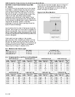
Fi
g
ure 7: Vent and Roof Detail
Model UHD[T][X][S][R] 150 - 250
Model UHD[X][S][R] 300 - 400
# of Elbows
30 ft (9.1 m)
1
25 ft (7.6 m)
2
20 ft (6.1 m)
3
15 ft (4.5 m)
4
10 ft (3.0 m)
5
Roof
Vent
Terminal
Listed Thim
b
le
Flashing
or Rain Collar
Vent
2" (5 cm) Air Gap
to Com
b
usti
b
le
Material
Summary of Contents for Combat UHD-Series
Page 2: ......
Page 4: ......
Page 8: ......
Page 46: ...UHD STANDARD DUCT FURNACE INSTALLATION OPERATION AND SERVICE MANUAL 38 of 57 14 1 General ...
Page 64: ...UHD STANDARD DUCT FURNACE INSTALLATION OPERATION AND SERVICE MANUAL 56 of 57 ...
Page 66: ......
Page 67: ......
Page 68: ......
Page 69: ......
Page 70: ......

